


1.20 1.20
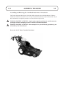
Assembling the Cutterhead Attachment
to the Power Unit
1. Position the cutterhead attachment on level
ground.
2. Remove the cutterhead drive cover.
3. Remove the power unit transmission guard.
4. Remove the engine drive belt from the
countershaft pulley.
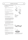
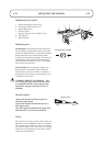
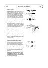
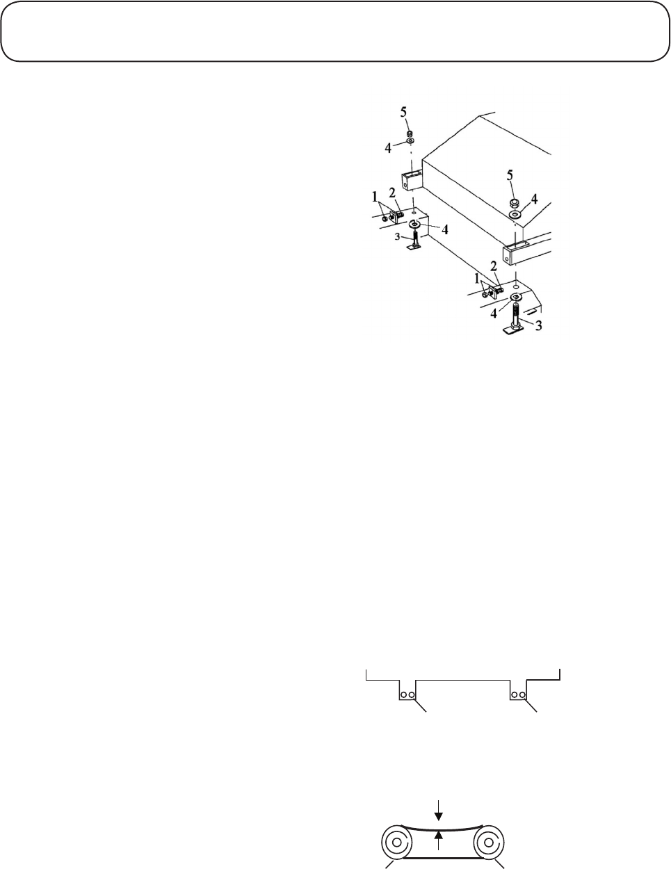
5. Loosen the lock nuts (item 1) and screw the
two tensioning bolts (item 2) fully forward
to provide maximum clearance for assembly.
Refer to Fig 1.
6. Position the cutterhead attachment close to
the front of the power unit.
7. One person should tilt the power unit down
at the front by holding and raising the handles,
whilst another person assembles the twin drive
belts between the cutterhead pulley and the
power unit countershaft pulley.
8. Lower the handlebars, align the power unit
to the cutterhead mountings and connect up
using the two bolts, washers and nyloc nuts
(items 3, 4 & 5). Do not fully tighten bolts
at this stage. Refer to Fig 1.
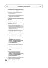
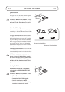
Note: The rotary attachment has two mounting
holes. Assemble using the right hand holes. Refer
to Fig 2, item A.
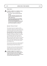
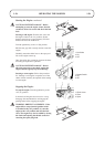
9. Adjust the two tensioning bolts (item 2, Fig 1)
equally to tension the twin drive belts. The
bolts are correctly tensioned when a deflection
of 13 mm is achieved using finger pressure.
Refer to Fig 3.
10. Tighten the locknuts (item 1) and nuts (item
5). Refer to Fig 1.
11. Re-check the belt tensions as previously
described and readjust if necessary. The twin
drive belts are matched but it is quite normal
for there to be slight differences in tension
between them.
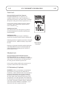
ASSEMBLING THE MOWER
Fig 1
Cutterhead
A A
Fig 2
1. Nut
2. Tensioning Bolt
3. Mounting Bolt
4. Washer
5. Nyloc Nut
.....................
........
"
"
13mm
""""""1" " " """"""""""2
Fig 3
1. Drive pulley attachment (cutterhead)
2. Countershaft pulley (Power unit)