


XI. ADJUSTMENT SECTION
Any adjustments or maintenance performed on the Model G1024 should be done with the power off,
the plug disconnected from the power source and only after all moving parts have come to a com-
plete stop. Make sure the machine is level and secure.
The following are recommended steps for adjusting the shaper. Please read the following adjust-
ment procedures to ensure the shaper is adjusted and ready for operation.
This section covers adjustment procedures for the following items. Read and follow these directions
carefully.
A. Fence
B. Spindle
C. Spindle Elevation
D. Cutter Direction
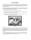
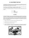
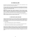
A. FENCE
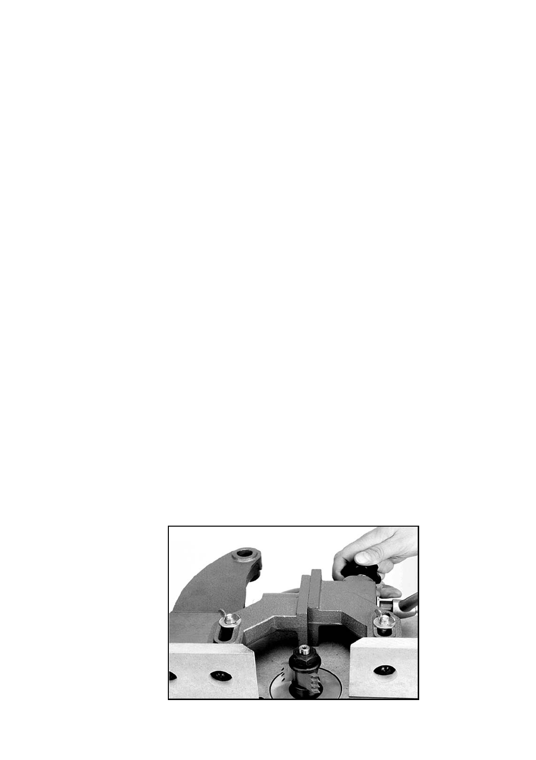
The Model G1024 Shaper’s fence uses a two-piece adjusting system. Each fence is adjustable to
compensate for different cutting thicknesses and special shaping applications, using the locking
knob at the rear of the shaper. See Figure 10. One turn of the knob moves the split fence approxi-
mately
3
/64" (.040"). When removing material from the whole face of your workpiece, the outfeed
fence should be adjusted to the proper offset to provide support for the workpiece as it passes over
the cutter. To adjust the fence:
1. Adjust the infeed fence so the cutter will remove the desired amount of stock.
2. Lock the infeed fence in position with the locking bolt.
3. Make a test sample and inspect the results.
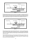
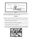
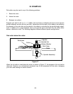
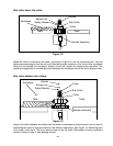
4. Adjust the outfeed fence to support the new profiled edge. Lock the outfeed fence into position
and re-test. See Figure 11 and Figure 12 for improper and proper outfeed fence positioning.
- 15 -
Figure 10