


9
Vektor-CD Centrifugal Laboratory Exhaust
®
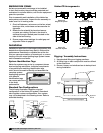
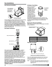
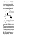
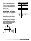
Disconnect is mounted to fan housing.
Transformer is mounted to bypass air plenum
near isolation damper actuator motor. For
systems that ship un-assembled because of
physical size, this connection at disconnect
from transformer must be field installed.
Wires with conduit and fitting are provided
pre-connected to transformer.
NOTE: If a Variable Frequency Drive is used to control fan speed,
transformer and actuator will not function properly when wired as
shown. Transformers must be wired independently from VFD control.
FIELD WIRING
FACTORY WIRING
LINE IN
208/230/460/575 V
3 PHASE
MOTOR
208/230/460/575/60/3
208/230/460/575 V
3 PHASE
DISCONNECT
POWER OPEN/SPRING CLOSE
ISOLATION DAMPER
ACTUATOR MOTOR
24/115 V
1 PHASE
TRANSFORMER
OPTIONAL ISOLATION
DAMPER CONTROL
208/230/460/575 V
1 PHASE
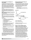
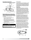
Applications with Variable Frequency
Drives (VFD)
For Vektor systems with single-point, three-phase
wiring per blower, the isolation damper actuator will
be powered via a step-down transformer, which is
wired to the fan disconnect, as shown in the diagram
above.
If fan flow (motor speed) is to be controlled using a
VFD, the reduced voltage and frequency supplied to
the fan will cause control problems with the isolation
damper actuator.
When a Vektor control sequence requires the use of a
VFD, it is suggested that the control contractor supply
the isolation damper actuator voltage — independent
of the power supplied to the Vektor fan motor.
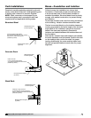
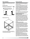
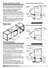
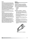
For Vektor Fans without a Weatherhood
A guard / cover is located on the side of the plenum
section. Removal of the guard / cover gains access to
the damper linkages, actuator (optional from factory)
and transformer (optional from factor). The entire
bypass damper assembly can be removed through
this opening. The isolation damper assembly can be
removed from its location by unbolting the frame from
the plenum and removing the flex connector.
If the Vektor units were not supplied with optional
actuators, the dampers have an extended jackshaft
for field mounting a customer supplied actuator.
Motor Disconnect Wiring &
Isolation Damper Wiring Diagram
Isolation Damper Control
Isolation dampers on de-energized fans are to be
closed to maintain system negative pressure and
prevent reverse “free-wheeling” of de-energized
blower(s). Isolation dampers shall be opened
immediately upon fan energizing.