


7
Vektor-CD Centrifugal Laboratory Exhaust
®
Fan Installation
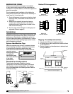
Fan Housing Installation
If the windband is shipped attached to the fan housing
or if the windband is secured to the fan housing
prior to mounting to the plenum, the fan / windband
assembly should be lifted by the lifting lugs located
on the fan housing. Do not lift this assembly by the
lifting lugs located on the windband. Connect fan
to plenum using Excelon™ flex connector found in the
Vektor-CD hardware kit.
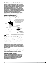
Four (4) lifting
lugs located
at top of
windband
Lifting lugs located at top
of bypass air plenum
Lifting lugs located on the
four corners of the base
Windband and nozzle assembly, if required:
1. Place windband on top of nozzle and align brackets with each other.
2. Bolt windband and nozzle together with fasteners provided.
3. Lift the assembly with the lifting lugs at the top of the windband and
place on top of the fan after the fan is placed. Use the fasteners
provided to fasten the nozzle flange to the fan flange.
Span determines the number of lifting lugs to use:
Span
12 inches or less Minimum of four (4) lifting lugs
12 to 18 inches Minimum of six (6) lifting lugs
18 inches or greater Minimum of eight (8) lifting lugs
Lines of attachment
are to be lifted in the
vertical direction to
prevent damage.
Spreader bars
are recommended.
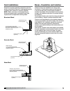
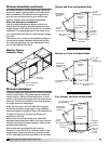
Windband Installation
Using the windband
lifting lugs, place
windband over blower
discharge, aligning
windband support
bracket holes with
bolt holes in blower
housing. Attach
windband to blower
discharge using 316
stainless steel bolts
(provided) through support brackets welded to the
inside of the windband. Use anti-seize gel (provided)
to prevent galling / welding of all stainless steel
fasteners.
Four (4) lifting
lugs located
at top of
windband
Lifting lugs located at top
of bypass air plenum
Lifting lugs located on the
four corners of the base
Windband and nozzle assembly, if required:
1. Place windband on top of nozzle and align brackets with each other.
2. Bolt windband and nozzle together with fasteners provided.
3. Lift the assembly with the lifting lugs at the top of the windband and
place on top of the fan after the fan is placed. Use the fasteners
provided to fasten the nozzle flange to the fan flange.
Span determines the number of lifting lugs to use:
Span
12 inches or less Minimum of four (4) lifting lugs
12 to 18 inches Minimum of six (6) lifting lugs
18 inches or greater Minimum of eight (8) lifting lugs
Lines of attachment
are to be lifted in the
vertical direction to
prevent damage.
Spreader bars
are recommended.
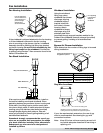
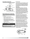
Fan Stack Installation
** Greenheck strongly recommends the use of guy wires on any system
that incorporates the usage of a stack extension and the subsequent
guy wires are to be designed and installed by others.
**Guy wire attachments
Fan Assembly
Stack Extension
If fan requires a stack or stack extension, install on
fan before installing nozzle and windband. Place
gasketing between any sections, blower housing and
initial stack. Use lifting lugs to position each piece
into place. Attach stack or stack extension to blower
housing using 316 stainless steel bolts (provided)
through flanges aligning bolt patterns. Use anti-
seize gel (provided) to prevent galling/welding of all
stainless steel fasteners.
Greenheck strongly recommends the use of guy
wires on any system that incorporates the usage
of a stack extension including inline attenuators.
Subsequent guy wires are to be designed and
installed by others.
1-1/4 inch thru-hole typical
NOTE: Guy wires to be supplied by others. Fastening to
building structure to be provided and engineered by others.
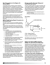
Guy Wire Locations
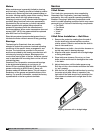
If your fan requires stack extensions, the use of guy
wires is recommended. See drawing for guy wire
connection locations.
Note: Keep 36 inches minimum spacing around unit
to provide adequate clearance for servicing or
repairing unit.
Bypass Air Plenum Installation
Four (4) lifting
lugs located
at top of
windband
Lifting lugs located at top
of bypass air plenum
Lifting lugs located on the
four corners of the base
Windband and nozzle assembly, if required:
1. Place windband on top of nozzle and align brackets with each other.
2. Bolt windband and nozzle together with fasteners provided.
3. Lift the assembly with the lifting lugs at the top of the windband and
place on top of the fan after the fan is placed. Use the fasteners
provided to fasten the nozzle flange to the fan flange.
Span determines the number of lifting lugs to use:
Span
12 inches or less Minimum of four (4) lifting lugs
12 to 18 inches Minimum of six (6) lifting lugs
18 inches or greater Minimum of eight (8) lifting lugs
Lines of attachment
are to be lifted in the
vertical direction to
prevent damage.
Spreader bars
are recommended.
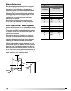
Span No. of Lifting Lugs
12 inches or less Minimum of 4 lifting lugs
12 to 18 inches Minimum of 6 lifting lugs
18 inches or greater Minimum of 8 lifting lugs
Span determines the number of lifting lugs to be used
during installation: