


5
Vektor-CD Centrifugal Laboratory Exhaust
®
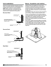
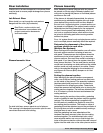
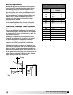
Riser Installation
Check curb or structural supports for levelness. Both
must be level to ensure proper drainage from plenum
and fan(s).
For side inlet fans, remove panel at end of plenum.
This opening is the designed connection spot for user
connected ductwork from building.
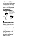
Lab Exhaust Riser
Riser duct(s) run up through the curb and are
flanged over the curb. (by contractor)
Roof Curb—anchor curb to roof
deck structure in accordance with
project construction documents
and local codes.
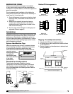
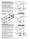
Plenum Assembly
Note: Gasketing material (shipped with fan) should
be placed on the top edge of already installed roof
curb prior to placing the plenum or individual plenum
sections on the curb.
If the plenum is shipped disassembled, the plenum
sections can be assembled together into one single
piece before lifting onto the roof and then fitted on
the roof curb / support structure, or each section can
be placed on individually. The method used would be
dependent on the lifting capacity for the equipment
on-site. If moving each piece separately onto the
roof curb or support structure, each section should
be joined to its mating part before moving another
section into place.
For a 1x1 system there is only a single plenum section
and no multiple plenum assembly would be required.
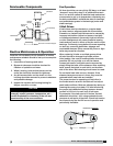
Determine the placement of the plenum
sections relative to each other
(Multiple Fan Systems)
When looking at the individual section one will notice
that each plenum section is missing at least one
side panel. These areas are the locations where the
sections are to be joined together. If you have two
plenum sections, then each one would be missing a
side panel. If you have a three-fan system, there are
three plenum sections. The two end plenum sections
would each be missing one side panel and the middle
section would not have panels on two sides. Please
refer to the submittal drawing for the orientation of
any Bypass Air Plenum (BAP) dampers or air inlet
locations.
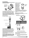
Putting the plenum together
After identifying the plenum sections arrangement
order, one of the two mating sections has weld nuts
on the inside of the plenum. The assembly hardware
(stainless steel bolts) required to join the sections
is located here for shipping purposes. These bolts
should be removed and set-aside prior to placing the
mating sections together. The bolts are located every
6 to 10 inches to provide the best seal between the
mating sections.
Before moving the sections into position, gasketing
must be installed to seal the plenum sections against
leakage. This silicone gasketing is supplied with
the fans and only needs to be applied to one of the
two mating plenum sections. The bands or strips of
gasketing should be attached around the perimeter of
the joining face and with an additional strip making a
triangular area in each corner.
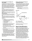
After the gasketing has been attached and the
hardware has been removed, place the two mating
sections together. The stainless steel bolts, which
were set aside earlier, are now run first through the
holes of the plenum section without the weld nuts and
tighten into the weld nuts on the other plenum section.
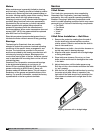
Plenum Isometric View