


Operation
24 Owner’s Manual for Stationary Emergency Generators
4.6.2— User Programmable
4.6.2.1—Start-Up Delay Timer
A programmable line interrupt delay (or Start-Up Delay) timer is provided. When utility voltage fails (falls below 60% of
nominal), the start-up delay timer is started. If the voltage rises above the Utility Volts Low threshold, the timer is reset.
If the utility voltage remains below the threshold during the duration of the timer, the unit cranks and starts.
NOTE: The factory default setting is five seconds, but is adjustable from 2 to 1500 seconds.
4.6.2.2—Warm-Up Delay Timer
A programmable Warm-Up Delay timer is provided. As soon as the generator starts, the warm-up timer is started.
When the warm-up timer expires, the control transfers load to the generator (through the transfer switch) if the utility
voltage is less than 80% of nominal. If utility voltage is greater than the threshold at expiration of the warm-up time, the
load is not transferred to the generator and a cool-down period begins. At the end of the cool-down period, the gener-
ator stops.
NOTE: The factory default setting is five seconds, but is adjustable from 5 to 1500 seconds.
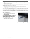
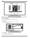
4.7 — USB Port for Firmware Updates
A USB port is located beneath the rubber flap on the control panel, and is provided for firmware updates. Firmware
updates must be performed by an Independent Authorized Service Dealer.
NOTE: The USB port is intended for use with a USB thumb drive only. The USB port is not intended for charging
devices such as phones or laptops. Do not connect any consumer electronics to the USB port.
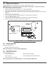
4.8 — Battery Charger
NOTE: The battery charger is integrated into the control panel module.
The battery charger ensures:
• Output is continually optimized to promote maximum battery life.
• Charging levels are safe.
NOTE: A warning message is displayed on the LCD screen when the battery requires service.
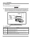
4.9 — Transfer Switch Automatic Operation
In AUTO, the generator starts automatically when utility source voltage drops below the preset level. Once the unit
starts, loads are transferred to the standby power source.
To select automatic operation:
1. Verify that the transfer switch main contacts are set to the UTILITY position (loads connected to the utility power
source).
2. Verify that normal UTILITY power source voltage is available to transfer switch terminal lugs N1, N2 and N3 (if
three phase).
3. Move the Main Circuit Breaker switch on the control panel up to the ON (Closed) position.
4. Press AUTO on the control panel. A green LED illuminates to confirm that the system is in the AUTO mode.