


6
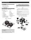
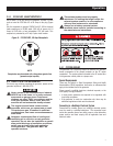
2.1.1 BATTERY CONNECTION
NOTE:
The battery shipped with the generator has been fully charged.
A battery may lose some of its charge when not in use for
prolonged periods of time. If the battery is unable to crank
the engine, plug in the 12V charger included in the accessory
box (see the Charging the Battery section). RUNNING THE
GENERATOR WILL CHARGE THE BATTERY.
The positive battery wire was deliberately left detached for
shipping. To operate the unit, attach this wire to the terminal on
the battery. Do not overtighten. Slide the attached rubber boot over
the battery post.
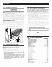
2.2 HOURMETER
The Hourmeter tracks hours of operation for scheduled
maintenance:
There will be a one time break in "CHG OIL" message that flashes
with the elapsed time in hours and tenths after the first 30 hours
of operation.
This message will actually begin flashing at 29 hours and disable
itself at 31 hours providing a two hour window to perform the
service.
There will be a subsequent "CHG OIL" message every 100 hours.
The message will flash one hour before and one hour after each
100 hour interval, again providing a two hour window to perform
service.
Every 200 hours the "SVC" icon on the lower left hand corner of
the display will flash. The message will flash one hour before and
one hour after each 200 hour interval providing a two hour window
to perform service.
When the hour meter is in the Flash Alert mode, the maintenance
message will always alternate with elapsed time in hours and
tenths. The hours will flash four times, then alternate with the
maintenance message four times until the meter resets itself.
100 hours - CHG OIL — Oil Change Interval (Every 100 hrs)•
200 hours - SVC — Air Filter Interval (Every 200 hrs)•
2.3 CORD SETS AND CONNECTION PLUGS
2.3.1 120 VAC, 20 AMP, GFCI DUPLEX RECEPTACLE
This is a 120 Volt outlet protected against overload by a 20 Amp
push-to-reset circuit breaker. Use each socket to power 120 Volt
AC, single phase, 60 Hz electrical loads requiring up to a combined
2400 watts (2.4 kW) or 20 Amps of current. Use only high quality,
well-insulated, 3-wire grounded cord sets rated for 125 Volts at 20
Amps (or greater).
Keep extension cords as short as possible, preferably less than
15 feet long, to prevent voltage drop and possible overheating of
wires.
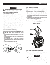
2.3.2 120/240 VAC, 30 AMP RECEPTACLE
Use a NEMA L14-30 plug with this receptacle (rotate to lock/
unlock). Connect a suitable 4-wire grounded cord set to the plug
and to the desired load. The cord set should be rated for 250 Volts
AC at 30 Amps (or greater) (Figure 4).
Use this receptacle to operate 120 Volt AC, 60 Hz, single phase
loads requiring up to 3600 watts (3.6 kW) of power at 30 Amps
or 240 Volt AC, 60 Hz, single phase loads requiring 6,500 to 8000
watts of power, depending on the model. The outlet is protected by
a 30 Amp circuit breaker.
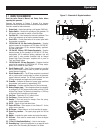
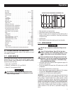
Figure 4 – Generator Receptacles
120 VAC 20A
GFCI RECEPTACLE
120/240 VAC 30A
RECEPTACLE
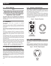
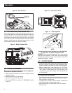
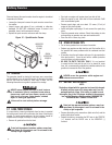
2.3.3 120 VAC, 30 AMP RECEPTACLE
Use a NEMA L5-30 plug with this receptacle. Connect a 3-wire
cord set rated for 125 Volts AC at 30 Amps (or greater) to the plug
(Figure 5).
Use this receptacle to operate 120 Volt AC, 60 Hz, single phase
loads requiring up to 3600 watts (3.6 kW) of power at 30 Amps.
The outlet is protected by a 30 Amp push-to-reset circuit breaker.
Figure 5 - 120 VAC, 30 Amp Receptacle
Operation