


5
2.1 KNOW THE GENERATOR
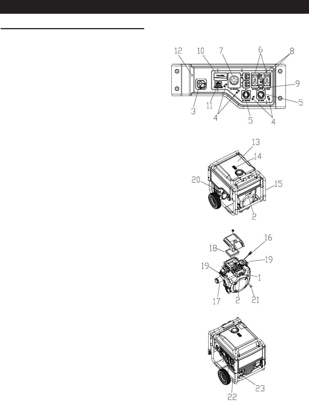
Read the entire Owner’s Manual and Safety Rules before
operating this generator.
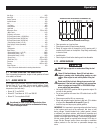
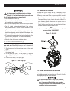
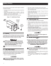
Compare the generator to Figures 3 through 6 to become
familiarized with the locations of various controls and adjustments.
Save this manual for future reference.
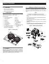
1. Choke Knob – Used when starting a cold engine (Pull/Push).
2. Engine Switch – Controls the operation of the generator. On
this electric start model the switch is Start/Run/Stop.
3. Fuel Shut Off – Valve between fuel tank and carburetor. Turn
off and run carburetor out of fuel for extended storage.
4. Panel LED's – Provide illumination of the control panel while
the generator is operating.
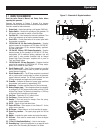
5. 120/240 Volt AC, 30 Amp Locking Receptacle – Supplies
electrical power for the operation of 120 and/or 240 Volt AC,
30 Amp, single-phase, 60 Hz, electrical lighting, appliance,
tool and motor loads.
6. 120 Volt AC, 20 Amp, GFCI Duplex Receptacle – Supplies
electrical power for the operation of 120 Volt AC, 20 Amp,
single-phase, 60 Hz electrical lighting, appliance, tool and
motor loads. It also provides protection with an Integral
Ground Fault Circuit Interrupter, complete with a press to
"Test" and "Reset" button.
7. 120/240 Volt AC, 50 Amp Receptacle – Supplies electrical
power for the operation of 120/240 Volt AC, 42 Amp, single-
phase, 60 Hz, welder or motor loads.
8. Circuit Breakers (AC) – Each 20 Amp receptacle is provided
with a push-to-reset circuit breaker to protect the generator
against electrical overload.
9. Circuit Breakers (AC) – The 30 Amp receptacle is protected
with a push-to-reset circuit breaker to protect the generator
against electrical overload. The 50 Amp receptacle and one
30 Amp receptacle use toggle reset circuit breakers.
10. PowerBar – Indicates the amount of power being used from
the generator; each section is approximately 25%
11. Hourmeter – Provides operating hours for Service Intervals.
12. Battery Charger Input – This receptacle allows the capability
to recharge the 12 VDC engine starting battery with the 12 Volt
Adaptor Plug Charger. The battery is protected by a 1.50 Amp
in-line fuse which is inside the control panel.
13. Fuel Tank – Tank holds 10 U.S. gallons of fuel.
14. Fuel Gauge – Shows fuel level in tank.
15. Handles – Pivot and retract for storage. Press the spring-
loaded button to move handles.
16. Oil Fill – Check oil level and add oil here.
17. Engine Oil Filter – Filters engine oil; see Section 3.1 for the
proper service intervals.
18. Air Cleaner – Filters intake air as it is drawn into the engine.
19. Spark Plug Location – The spark plugs ignite the Air/Fuel
Mixture.
20. Muffler – Includes the spark arrestor and quiets the engine.
21. Oil Drain – Drain valve to remove used oil from the engine
crankcase.
22. 12 Volt (18 Amp Sealed Battery) – Used to start engine.
23. Grounding Lug – Ground the generator to an approved earth
ground here. See "Grounding the Generator" for details.
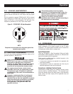
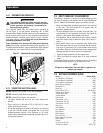
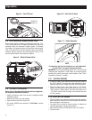
Figure 3 – Generator & Engine Locations
Operation