


Not for
Reproduction
31
Initial Start‑up (No Load)
The unit has been set-up for NG operation at the factory. Fuel
conversion, if needed, must be completed prior to performing
these steps. See Fuel Conversion.
Before operating the generator or placing it into service,
inspect the entire installation carefully. Then begin testing the
system without any electrical loads connected, as follows:
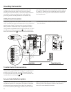
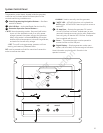
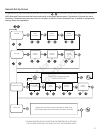
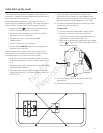
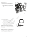
1. Remove 6 screws (A) that secure control box cover to
enclosure to expose unit’s circuit breaker.
2. Connect an accurate frequency meter to line side of
generator’s main circuit breaker.
3. Set generator’s main circuit breaker to ON
(closed) position.
4. Install 15 Amp fuse in control board.
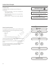
5. Press and hold MANUAL button on control board for 3
seconds. Engine will start.
When the generator is started for the very first time, it will
require that air in the gaseous fuel lines be purged. This may
cause the engine to run roughly for a few minutes.
6. Listen for unusual noises, vibration or other indications
of abnormal operation. Check for oil leaks while engine
runs.
7. Let engine warm up for about 5 minutes to allow internal
temperatures to stabilize.
8. Check generator output at load side of circuit breaker.
Voltage should be 238 - 242 Volts, frequency should be
59.0 - 61.0 Hz.
9. Check generator output between one generator
connection lug and neutral lug, then between other
generator connection lug and neutral lug. In both cases,
voltage reading should be between 119 - 121 Volts.
10. If voltage is outside of these limits, the AVR may need
adjustment (this is not typical).
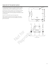
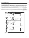
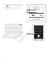
To adjust AVR:
A. Connect voltmeter as described in step 2 above.
B. Remove 4 screws securing control panel and
carefully lift control panel to expose AVR. (Warning
components on control board are live)
C. While observing voltmeter, adjust alternator voltage
Control (B) for 240 volts. DO NOT adjust either of the
other alternator controls.
11. Push and hold OFF BUTTON on control board until
engine stops.
12. Reinstall control panel with 4 screws.
A
A
B
B