


Not for
Reproduction
15
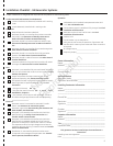
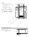
Electrical and Fuel Inlet Locations
Electrical and Fuel Inlet Locations
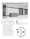
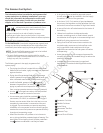
The 3/4 inch N.P.T. fuel inlet connector (B) and 2 inch
electrical inlet location (C) is shown.
B
C
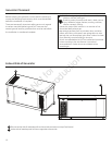
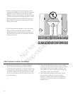
Concrete Slab
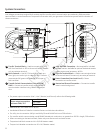
At the appropriate location, construct a concrete slab:
• 28 day compression strength of 3000 psi (200 MPa)
• Minimum 5” (13 cm) thick
• Minimum 6” (15 cm) wider than enclosure on all sides
(shown as D in figure)
• Strengthen slab with No. 6 reinforcing bars
(on 12” (30.5 cm) centers) or 8 ga. steel wire fabric
(6” (15 cm) centers).
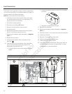
Attach unit to slab at four corner locations (A) with minimum
5/16”(8 mm) diameter masonry anchor bolts long enough to
secure the unit.
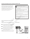
The fuel inlet location (B), the wire entry location (C), the
concrete slab (D), and the exhaust outlet (E) are shown for
reference.
B C
D
A
E
A
42” (106.68 cm)
Concrete Slab (Ref)
30” (76.20 cm)
Base
27.73” (70.43 cm)
Anchor Hole
7.4”
(18.80 cm)
2X 73.43”
(186.51 cm)
32.3” (82.04 cm)
Roof Overhang
18.9”
(48.00 cm)
70”
(177.80 cm)
Base
68”
(172.72 cm)
Anchor Hole
71”
(180.34 cm)
Roof
Overhang
82”
(208.28 cm)
Concrete
Slab (Ref)
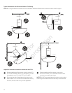
C
D
B
E
6” (15.24 cm)
Min. Overhang
All Sides
29.8”
(75.69 cm)
2.0”
(5.08 cm)
7.4”
(18.80 cm)
18.9”
(48.00 cm)
C
B