


Not for
Reproduction
24
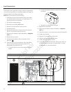
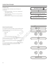
Service Code Detection System
The generator may have to run for long periods of time with
no operator present. For that reason, the system is equipped
with sensors that automatically shut down the generator in
the event of potentially damaging conditions, such as low oil
pressure, high temperature, over speed, and other conditions.
Refer to Service Code Detection System in the operator’s
manual for more detailed information.
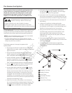
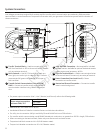
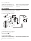
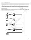
Utility Circuit Connection
“240V Utility” leads must be routed in conduit. The “240V
Utility” leads deliver power to the generator’s circuit board and
optional water heater. This power also charges the battery.
When power on these leads is lost, the generator will start.
Using installer-supplied #14 AWG minimum 300 volt 75°C-90°C
wire †, connect the two-pin terminal A in the control panel
box to the fuse terminals B in the automatic transfer switch.
† Use National electric code for correction factors and wire
size calculations.
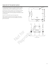
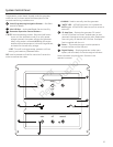
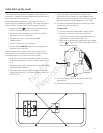
The generator must be installed as part of a system that
includes a listed transfer switch, with neutral to ground
bonding at the transfer switch in accordance with installation
instructions. Unless mandated by local code, additional
grounding to earth at the generator is not required. Any
grounding at generator must use metal piercing lock washers
(or equal), UL listed terminals installed per terminal supplier’s
instructions, and comply with national electrical codes and
local requirements.
Grounding the Generator
Transfer Switch Communication
Using installer supplied #18 AWG twisted pair conductors, no
greater than 200 ft in length, connect Tx Rx and Tx Rx GND
from the generator terminal block C to T/R and GND on the
transfer switch control board D .
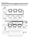
C
D
B
A
LINE 1
LINE 2
GROUND
NEUTRAL
]
]
UTILITY A
UTILITY B
NO
COMM
NC
TxRx
TxRx GND
+LED
GND
N/C
]
]
]
GENERATO
RT
RANSFER SWITCH
D
A
C
B
GENERATOR TRANSFER SWITCH