


28
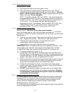
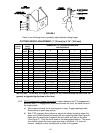
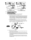
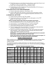
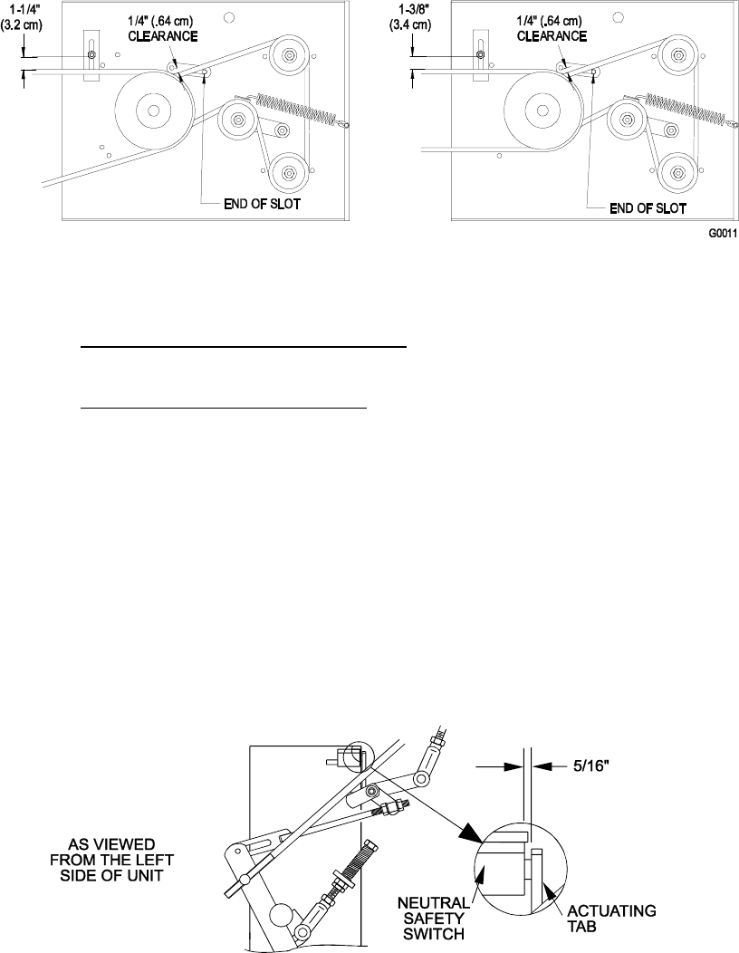
Note: These drawings are viewed from underneath the engine deck
FIGURE 9 FIGURE 10
36" BELT GUIDE LOCATION 48" BELT GUIDE LOCATION
4.2.8 Pump Drive Belt Tension Adjustment
:
No adjustment necessary.
4.2.9 Hydro Drive Linkage Adjustment
:
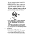
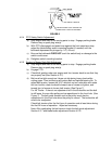
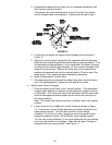
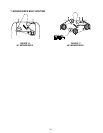
a) Adjust Speed Control Linkage and neutral safety switch
1. Stop engine and wait for all moving parts to stop.
2. Move the speed control lever (located on the console) to the full forward
position and check the orientation of the tabs on the ends of the speed
control crank (Figure 11). These tabs should be pointing straight down
at the 6 o’clock position or slightly forward. Adjust the threaded yoke at
the bottom of the speed control linkage (See Figure 11) until the tabs
are positioned correctly.
3. Pull the speed control lever back to neutral. Check that the neutral
safety switch actuating tab has depressed the plunger of the switch so
that there is about 5/16” (.79 cm) between the tab and the switch. See
Figure 11. If necessary, move the switch fore and aft.
FIGURE 11
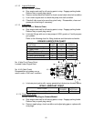
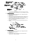
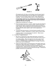
b) Adjust Neutral Control Linkages
1. Raise the rear of the machine up onto jack stands high enough to raise
the drive wheels off of the ground.
2. Start the engine and move the throttle ahead to the full throttle position.
Place the neutral lock latches in the “forward” position as shown in Figure
2. Release the park brake and move the speed control lever to the “mid-
speed” position.
Note: The OPC levers must be held down and the park brake must be
disengaged whenever the speed control lever is moved out of neutral or
the engine will kill.
(.79 cm)