


11
2.9 DECK
2.9.1 Cutting Width:
36” 48”
35.38 in. (89.9 cm) 47.24 in. (120.0 cm)
2.9.2 Discharge: Right Side
2.9.3 Blade Size:
36” 48”
Length
18.00 in. (45.7 cm) 16.25 in. (41.3 cm)
Qty
2 3
2.9.4 Type of Drive: Manual engagement of belt with over-center lock. Belt tension is
adjustable via turnbuckle.
2.9.5 Blade Brake: When the PTO engagement control is move to the disengaged
position a friction brake pad stops the rotation of the blades.
2.9.6 Deck Mounting: Bolted directly to the engine deck.
2.9.7 Cutting Height: Adjusts in 1/4” (.63 cm) increments from 1” (2.5 cm) to 4 1/4”
(10.8 cm).
2.10 DIMENSIONS
2.10.1 Overall Width:
36” 48”
Discharge chute down 47.0” (119.4 cm) 57.9” (147.1 cm)
Discharge chute up
(Transport only)
36.4” (92.5 cm) 48.1” (122.2 cm)
2.10.2 Overall Length:
36” 48”
77.3” (196.3 cm) 72.3” (183.6 cm)
2.10.3 Curb Weight:
36” 48”
498 lbs. (226 kg) 551 lbs. (250 kg)
2.10.4 Overall Height:
36” 48”
43.2” (109.7 cm) 43.2” (109.7 cm)
2.10.5 Tread Width:
36” 48”
(to outside of tires)
35.6” (90.4 cm) 40.4” (102.6 cm)
2.11 TORQUE REQUIREMENTS
BOLT LOCATION TORQUE
Blade/Cutter Housing Spindle Bolt ................................ 75-85 ft-lbs. (102-115 N-m)
Caster Bracket Mounts.................................................. 30-35 ft-lbs. (41-47 N-m)
Cutter Deck/Engine Deck Mount ................................... 30-35 ft-lbs. (41-47 N-m)
Engine Mounting Bolts .................................................. 15-20 ft-lbs. (20-27 N-m)
Wheel Lug Nuts ............................................................ 90-95 ft-lbs. (122-129 N-m)
Wheel Hub Slotted Nut.................................................. minimum 100 ft-lbs (136 N-m)
3. OPERATION INSTRUCTIONS
3.1 CONTROLS
3.1.1 Familiarize yourself with the controls and operation of the unit.
Carefully read the following information about the controls and their operation.
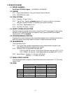
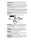
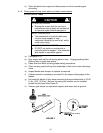
3.1.2 Operator Presence Control (OPC) Levers
: Located on the upper handle
assembly directly above the handle grips (See Figure 1). When these levers are
depressed, the OPC system senses that the operator is in the normal
operator's position. When the levers are released, the OPC system senses
that the operator has moved from the normal operating position and will kill
the engine if either the speed control lever is not in the neutral position or the
PTO is engaged.