


25
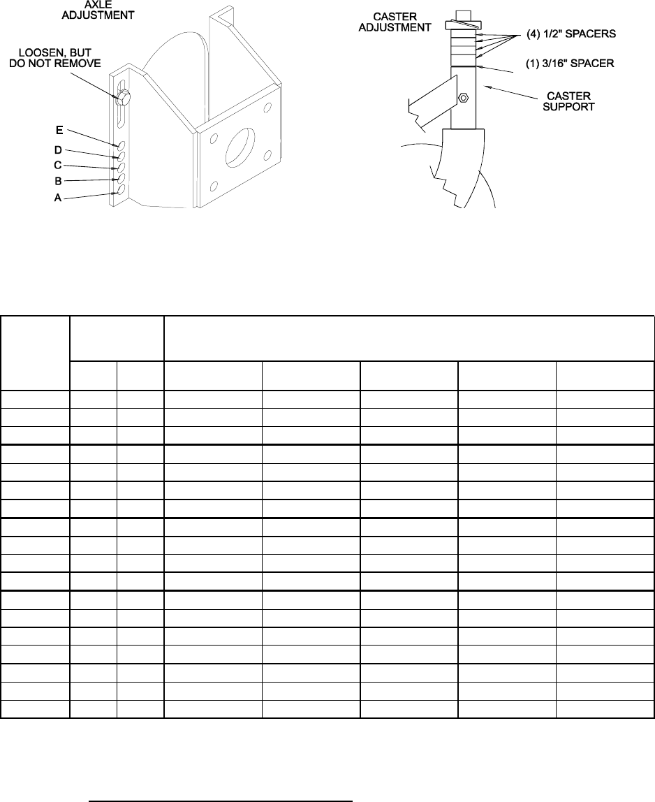
FIGURE 5
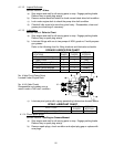
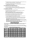
Refer to the following chart to properly adjust desired cutting height.
CUTTING HEIGHT ADJUSTMENT (1" (2.5 cm) to 4 1/4" (10.8 cm))
AXLE
POSITION
(FIG. 20)
# OF SPACERS
BELOW
CASTERS
NUMBER OF 1/4" (.64 cm)BLADE SPACERS
BELOW SPINDLE
1/2"
(1.2cm)
3/16"
(.48cm)
4 3 2 1 0
A 0 0 1" (2.5 cm) 1 1/4" (3.2 cm) 1 1/2" (3.5 cm) 1 3/4" (4.4 cm) 2" (5.0 cm)
A 0 1 1 1/8" (2.9 cm) 1 3/8" (3.5 cm) 1 5/8" (4.1 cm) 1 7/8" (4.8 cm) 2 1/8" (5.4 cm)
A 1 0 1 3/8" (3.5 cm) 1 5/8" (4.1cm) 1 7/8" (4.8 cm) 2 1/8" (5.4 cm) 2 3/8" (6.0 cm)
B 0 1 1 3/8" (3.5 cm) 1 5/8" (4.1cm) 1 7/8" (4.8 cm) 2 1/8" (5.4 cm) 2 3/8" (6.0 cm)
B 1 0 1 5/8" (4.1 cm) 1 7/8" (4.8 cm) 2 1/8" (5.4 cm) 2 3/8" (6.0 cm) 2 5/8" (6.7 cm)
B 1 1 1 3/4" (4.4 cm) 2" (5.0 cm) 2 1/4" (5.7 cm) 2 1/2" (6.4 cm) 2 3/4" (7.0 cm)
B 2 0 2" (5.0 cm) 2 1/4" (5.7 cm) 2 1/2" (6.4 cm) 2 3/4" (7.0 cm) 3" (7.6 cm)
C 1 1 1 7/8" (4.8 cm) 2 1/8" (5.4 cm) 2 3/8" (6.0 cm) 2 5/8" (6.7 cm) 2 7/8" (7.3 cm)
C 2 0 2 1/8" (5.4 cm) 2 3/8" (6.0 cm) 2 5/8" (6.7 cm) 2 7/8" (7.3 cm) 3 1/8" (7.9 cm)
C 2 1 2 1/4" (5.7 cm) 2 1/2" (6.4 cm) 2 3/4" (7.0 cm) 3" (7.6 cm) 3 1/4" (8.3 cm)
C 3 0 2 1/2" (6.4 cm) 2 3/4" (7.0 cm) 3" (7.6 cm) 3 1/4" (8.3 cm) 3 1/2" (8.9 cm)
D 2 1 2 3/8" (6.0 cm) 2 5/8" (6.7 cm) 2 7/8" (7.3 cm) 3 1/8" (7.9 cm) 3 3/8" (8.6 cm)
D 3 0 2 1/2" (6.4 cm) 2 3/4" (7.0 cm) 3" (7.6 cm) 3 1/4" (8.3 cm) 3 1/2" (8.9 cm)
D 3 1 2 3/4" (7.0 cm) 3" (7.6 cm) 3 1/4" (8.3 cm) 3 1/2" (8.9 cm) 3 3/4" (9.5 cm)
D 4 0 3" (7.6 cm) 3 1/4" (8.3 cm) 3 1/2" (8.9 cm) 3 3/4" (9.5 cm) 4" (10.1 cm)
E 3 1 2 7/8" (7.3 cm) 3 1/8" (7.9 cm) 3 3/8" (8.6 cm) 3 5/8" (9.2 cm) 3 7/8" (9.8 cm)
E 4 0 3 1/8" (7.9 cm) 3 3/8" (8.6 cm) 3 5/8" (9.2 cm) 3 7/8" (9.8 cm) 4 1/8" (10.5cm)
E 4 1 3 1/4" (8.3 cm) 3 1/2" (8.9 cm) 3 3/4" (9.5 cm) 4" (10.1 cm) 4 1/4" (10.8cm)
IMPORTANT: To achieve the highest quality of cut, blades should be level with the
ground, or tipped slightly down at the front.
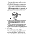
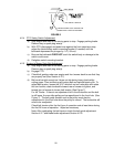
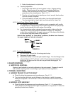
4.2.3 PTO Engagement Linkage Adjustment
: Located between the PTO engagement
bellcrank and PTO engagement assist arm beneath the front, left hand corner of
the engine deck.
a) Stop engine and wait for all moving parts to stop. Engage parking brake.
Remove key or spark plug wire(s).
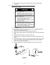
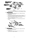
b) With PTO engaged (lever pulled up, adjust the linkage length to where the
lower end of the bellcrank just clears the axle support gusset (See Figure 6).
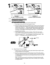
Make sure the assist arm is against the rear assist arm stop on the deck
(See Figure 7). Push the lever down to the disengaged position. The assist
arm should contact the front assist arm stop on the deck. If it does not
contact, readjust so that the bellcrank is closer to the gusset.
(1.3 cm)
(.47 cm)