


13
Pull the lever up and rearward to engage the brake.
Push the lever forward and down to disengage the brake.
When parking on a steep slope, the wheels must be chocked or blocked in
addition to the brake being engaged. The unit must be tied down and brake
engaged when transporting.
Park brake must be disengaged before the speed control lever is moved out of
neutral or PTO is engaged or engine will kill.
3.1.11 Fuel Shut-Off Valve
: Installed in the fuel line midway between the tank and
engine. The fuel shut-off valve is used to shut off the flow of fuel when parking
inside a building, during transportation to and from the job sites, and when the
machine will not be used for a few days.
Rotate valve 1/4 turn clockwise to shut fuel off.
Rotate valve 1/4 turn counter-clockwise to turn fuel on.
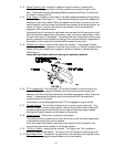
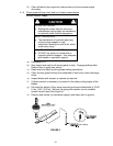
3.1.12 Drive Wheel Release Valves
: Located on the top rear corner of the hydrostatic
pumps. Drive wheel release valves are used to release the hydro-static drive system
to allow the machine to be moved by hand without the engine running. With a 5/8”
wrench, turn valves one turn counterclockwise to release the drive system.
Turn clockwise to reset the drive system. Do Not over-tighten.
3.1.13 Cold Start Kit
: Located on the right hand side of engine deck, below and slightly
ahead of the hydro control shield. The cold start kit is used to ease the starting
of the unit in cold weather or when the unit has not been operated for a period of
time. The cold start kit moves the idler pulley away from the pump belt, releasing
the tension on the belt which allows the engine to turn over with less resistance.
See Section 3.3.2.
3.1.14 Tracking Adjustment Knob
: Located on the right-hand side of the rear of the fuel
tank support. Can be adjusted so that machine will “track” straight ahead with
drive levers released.
3.2 PRE-START
3.2.1 Fill fuel tank. For best results use only clean fresh regular grade unleaded
gasoline with an octane rating of 87 or higher. Regular grade leaded gasoline
may also be used; however, combustion chamber and cylinder head will require
more frequent service. See Engine Owner's Manual.
Do not add oil to gasoline.
Do not overfill fuel tank. Never fill the fuel tank so that the fuel level rises above a
level that is 1/2” (1.3 cm) below the bottom of the filler neck to allow for fuel
expansion and prevent fuel spillage.
3.2.2 Refer to Maintenance and Adjustment Section 4.1 and perform all of the
necessary inspection and maintenance steps.
3.2.3 Make sure you understand the controls, their locations, their functions, and their
safety requirements.
3.3 OPERATING INSTRUCTIONS
3.3.1 Read the Engine Owner’s Manual carefully for detailed operating instructions
and maintenance regarding the engine.
Before attempting to operated the unit, refer to Section 1 (Safety) and follow all
safety, operating, and preparation guidelines as stated in that section.
3.3.2 Starting Engine
: Operator must have PTO disengaged and speed control lever
in neutral.
Lock drive levers in neutral and engage park brake.
Open fuel shut-off valve.