


- 34 -
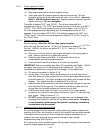
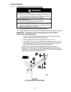
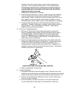
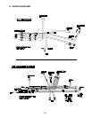
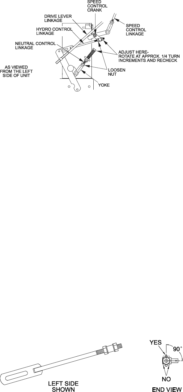
FIGURE 13
HYDRO DRIVE LINKAGE ADJUSTMENT
4. Loosen the nut against the neutral control linkage yoke (See Figure 13).
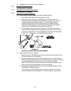
5. Adjust the neutral control linkage until the respective drive wheel stops
when the lever is pulled against the neutral spring (neutral position). Turn
the adjusting bolt approximately 1/4 turn clockwise if the wheel is turning
in reverse or turn the bolt approximately 1/4 turn counter-clockwise if the
wheel is turning forward. Release the drive lever to the forward drive
position and squeeze back into the neutral position. Check to see if the
wheel stops. If not, repeat the above adjustment procedure.
6. Make this adjustment on both sides.
7. After adjustments are made and the wheels stop when the drive levers
are in the neutral position, tighten the nuts against the yokes.
c) Adjust Hydro Control Linkages:
1. Place the speed control lever in the “neutral” position.
Note: Neutral lock latches should still be “unlocked” and in the “forward”
position.
This adjustment is again made with rear of machine on jack stands and
engine running at full throttle. OPC levers will have to be held down
whenever speed control lever is moved out of the neutral position.
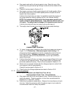
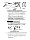
2. Loosen the front nut on left hydro control linkage as shown in Figure
13. Turn the rear control linkage adjusting nut counter-clockwise until
wheel rotates forward. Turn the rear nut of left control link clockwise
1/4 of a turn at a time, stopping to move the speed control forward and
back to neutral, until left wheel stops rotating forward. Turn the rear nut
an additional 1/2 turn and tighten the front nut making sure not to put a
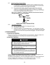
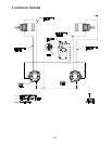
bind on the linkage. Make sure flat part of linkage is perpendicular to
pin part of swivel (See Figure 14).
FIGURE 14
HYDRO CONTROL LINK/SWIVEL ADJUSTMENT
After adjusting the left hydro control linkage, move the speed control
lever to the mid-speed position and then back to the neutral position.