Operation
1. Stop the machine and move the drive levers to
the neutral lock position.
2. Disengage the PTO.
3. Engage the park brake.
4. Stop the engine, remove the key and wait for all
moving parts to stop.
5. After adjusting the height of cut, adjust the
anti-scalp rollers by removing the nyloc nut.
6. Adjust the anti-scalp rollers for the normal
operating conditions. Place rollers in one of
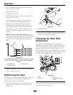
the positions shown in Figure 12. Rollers will
maintain 3/4 inches (19 mm) clearance to the
ground to minimize gouging and roller wear or
damage.
Note: For Maximum Deck Flotation, place
the rollers one hole position lower. Rollers should
maintain 1/4 inch (6.35 mm) clearance to the
ground. Do Not adjust rollers to support the
deck.
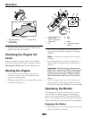
Figure 12
For cutting heights above 3 1/2 inches (38 mm) use the
bottom hole. The rollers will still be effective against
scalping.
1. Anti-scalp roller
mounting bracket
2. Cutting height
7. Torque hardware to 27-33 ft-lb (37-45 N-m) or
loss of roller may result.
Positioning the Seat
The seat can move forward and backward. Position
the seat where you have the best control of the
machine and are most comfortable.
1. Push the adjustment lever towards the center of
the machine to release the seat adjuster track
(Figure 13).
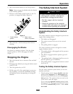
Figure 13
1. Adjustment lever
2. Move the seat to the desired position and release
the lever to lock in that position.
Changing the Seat Ride
Suspension
The number of seat springs can be changed to
maximize rider comfort. More springs should be used
with heavier operators and on rough terrain. Fewer
springs should be used with lighter operators and
when mowing smooth, well established lawns. Always
keep the number of springs on the left and right side
the same when adding and removing springs.
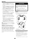
Figure 14
1. Bolt 3. Nut
2. Spring
4. Additional mounting
holes
Up to ve springs can be secured to the seat box with
a nut and bolt, see Figure 14.
24


