


Operation
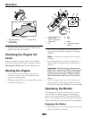
Product Overview
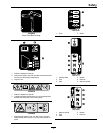
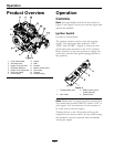
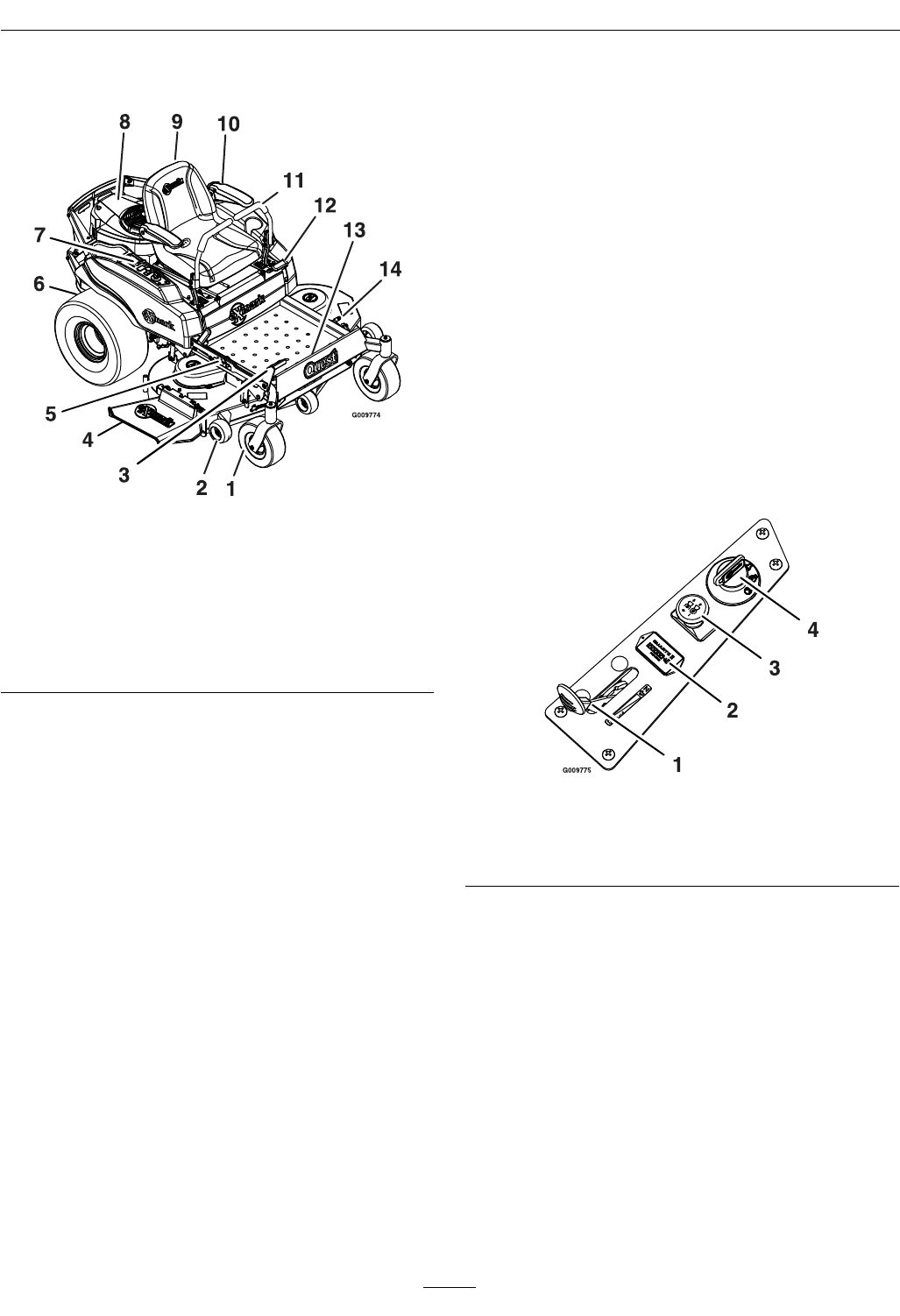
Figure 3
1. Front caster wheel 8. Engine
2. Anti-scalp roller
9. Seat
3. Height of cut foot lever
10. Armrest
4. Discharge deector
11. Motion control levers
5. Height of cut adjustment
12. Park brake
6. Rear drive wheel 13. Footrest
7. Control panel 14. Washout tting
Operation
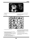
Controls
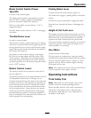
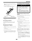
Note: Become familiar with all of the controls in
Figure 3 and Figure 4 before you start the engine and
operate the machine.
Ignition Switch
Located on control panel.
The ignition switch is used to start and stop the
engine. The switch has three positions “OFF”,
“RUN” and “START” ( Figure 4). Insert key into
switch and rotate clockwise to the “ON” position.
Rotate clockwise to the next position to engage the
starter (key must be held against spring pressure in
this position).
Figure 4
1. Throttle/Choke lever
3. Blade control switch
(power take-off)
2. Hour meter 4. Ignition switch
Note: Brake must be engaged, motion control levers
out (neutral lock position) and PTO switch “OFF” to
start engine. (It is not necessary for the operator to
be in the seat to start the engine.)
Turning the key to the Off position will stop the
engine; however, always remove the key when leaving
the machine to prevent someone from accidentally
starting the engine
16