


Maintenance
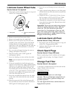
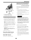
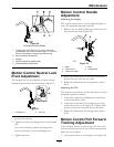
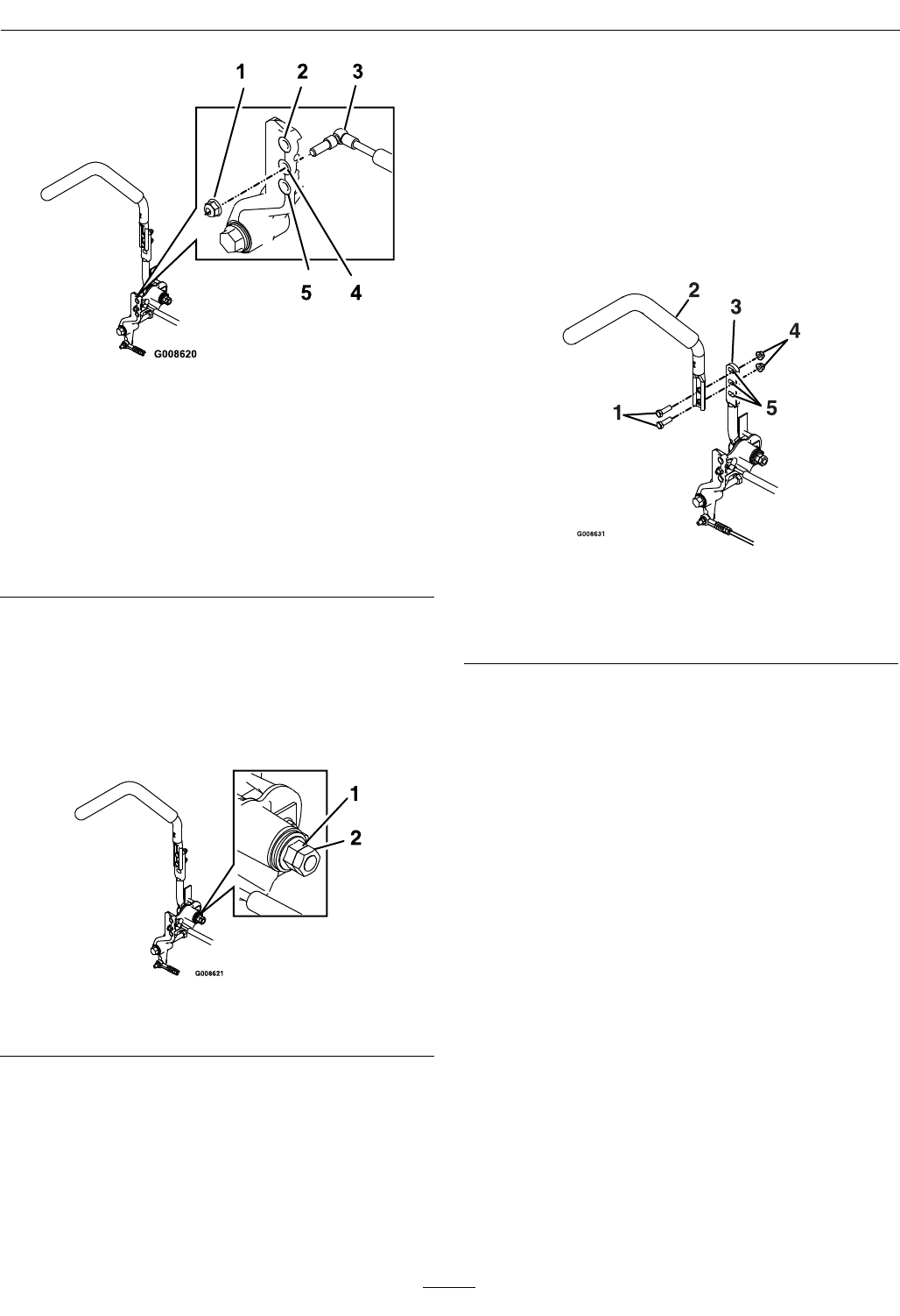
Figure 36
RH Motion Control Shown
1. Torque nyloc nut to 200 in-lb (16.7 ft-lb). Bolt must
protrude past end of nyloc nut after torque. A T-40 Torx
bit will be necessary to hold the stud from turning.
2. Most resistance (rmest feel)
3. Damper
4. Medium resistance (medium feel)
5. Least resistance (softest feel)
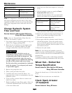
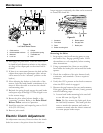
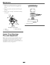
Motion Control Neutral Lock
Pivot Adjustment
The anged nut can be adjusted to obtain a more
desired motion control lever resistance (Figure 37).
Figure 37
1. Flanged nut 2. Jam nut
1. Loosen the jam nut.
2. Tighten or loosen the anged nut to the desired
feel.
For more resistance, tighten the anged nut.
For less resistance, loosen the anged nut
3. Tighten jam nut.
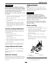
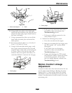
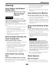
Motion Control Handle
Adjustment
Adjusting the height:
The motion control levers can be adjusted higher or
lower for maximum operator comfort.
1. Remove the two bolts holding the control lever to
the control arm shaft (
Figure 38).
Figure 38
1. Bolts 4. Nuts
2. Control lever 5. Slotted holes
3. Control arm shaft
2. Move the control lever to the next set of holes.
Secure the lever with the two bolts.
3. Repeat the adjustment for the opposite control
lever.
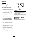
Adjusting the Tilt
The motion control levers can be tilted fore or aft for
maximum operator comfort.
1. Loosen the upper bolt holding the control lever
to the control arm shaft.
2. Loosen the lower bolt just enough to pivot the
control lever fore or aft
Figure 38. Tighten both
bolts to secure the control in the new position.
3. Repeat the adjustment for the opposite control
lever.
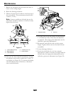
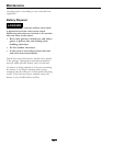
Motion Control Full Forward
Tracking Adjustment
If the machine travels or pulls to one side when the
motion control levers are in the full forward position,
adjust the cover plates.
1. Loosen the screws on a cover plate (see Figure 39).
45