


Maintenance
WARNING
Engine must be running and drive wheels must
be turning so adjustments can be performed.
Contact with moving parts or hot surfaces may
cause personal injury.
Keep ngers, hands, and clothing clear of
rotating components and hot surfaces.
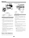
1. Prior to starting the engine, push the deck lift
pedal and remove the height of cut pin. Lower
deck to the ground.
2. Raise the rear of machine up and support with
jack stands (or equivalent support) just high
enough to allow drive wheels to turn freely.
3. Remove the electrical connection from the seat
safety switch, located under the bottom cushion
of the seat. The switch is a part of the seat
assembly.
4. Temporarily install a jumper wire across the
terminals in the connector of the main wiring
harness.
5. Start engine. Brake must be engaged and
motion control levers out to start engine.
Operator does not have to be in the seat
because of the jumper wire being used. Run
engine at full throttle and release brake.
6. Run the unit at least 5 minutes with the drive
levers at full forward speed to bring hydraulic oil
up to operating temperature.
Note: The motion control lever needs to be in
neutral while making any necessary adjustments.
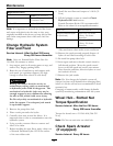
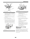
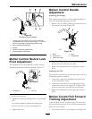
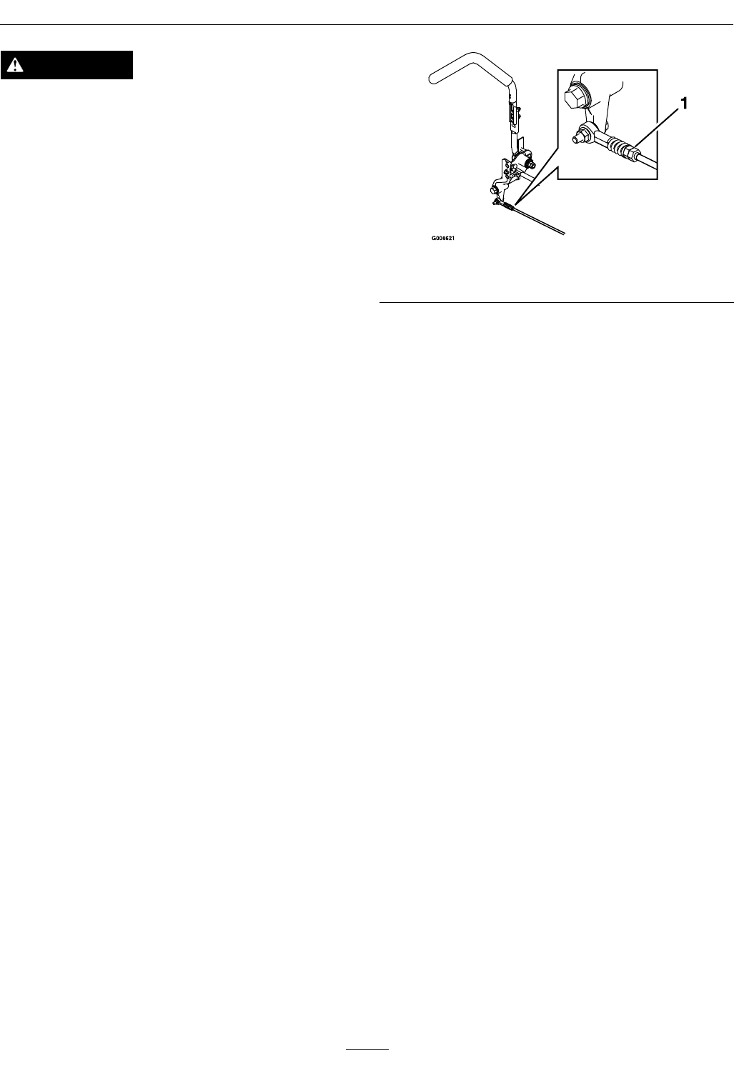
7. Bring the motion control levers into the neutral
position. Adjust pump control rod lengths
by rotating the double nuts on the rod in the
appropriate direction until the wheels slightly
creep in reverse (
Figure 35). Move the motion
control levers to the reverse position and while
applying slight pressure to the lever allow the
reverse indicator springs to bring the levers back
to neutral. The wheels must stop turning or
slightly creep in reverse.
Figure 35
1. Double nuts
8. Shut off unit. Remove jumper wire from wire
harness and plug connector into seat switch.
9. Remove the jack stands.
10. Raise the deck and re-install the height of cut pin.
11. Check that the machine does not creep in neutral
with the park brakes disengaged.
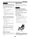
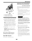
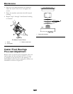
Motion Control Damper
Adjustment
The top damper mounting bolt can be adjusted to
obtain a more desired motion control lever resistance.
See Figure 36 for mounting options.
44