


Maintenance
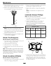
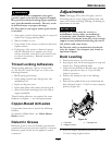
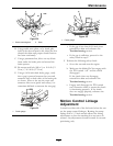
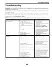
Figure 32
1. Brake mounting bolt
2. Shim
B. Using needle nose pliers, or by hand, take
hold of the tab and remove the shim (Do Not
discard the shim until proper clutch function
has been conrmed).
C. Using a pneumatic line, blow out any debris
from under the brake pole and around the
brake spacers.
D. Re-torque each bolt (M6 x 1) to 10 ft-lb (13
N-m) +/-0.5 ft-lb (0.7 N-m).
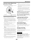
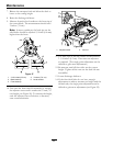
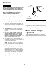
E. Using a 0.010 inch thick feeler gauge, verify
that a gap is present between the rotor and
armature face on both sides of the brake pole
as shown. (Due to the way the rotor and
armature faces wear (peaks and valleys) it is
sometimes difcult to measure the true gap.)
G011733
1
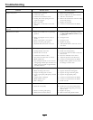
Figure 33
1. Feeler gauge
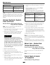
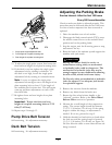
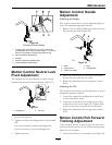
Figure 34
1. Feeler gauge
• If the gap is less than 0.010 inch, then
reinstall the shim and reference the
Troubleshooting section.
• If the gap is sufcient, proceed to the
safety check in step
F.
F. Perform the following safety check:
a. Sit on the seat and start the engine.
b. Make sure the blades Do Not engage with
the PTO switch “off ” and the clutch
disengaged.
If the clutch does not disengage,
reinstall the shim and reference the
Troubleshooting section.
c. Engage and disengage the PTO switch
ten consecutive times to ensure the clutch
is functioning properly. If the clutch
does not engage properly, reference the
Troubleshooting section.
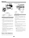
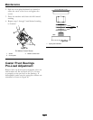
Motion Control Linkage
Adjustment
Located on either side of the fuel tank, below the seat
are the pump control linkages. Rotating the pump
linkage with a 1/2 inch wrench allows ne tuning
adjustments so that the machine does not move in
neutral. Any adjustments should be made for neutral
positioning only.
43