


Operation
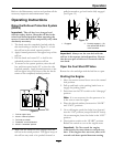
To turn right, release pressure on the RH motion
control lever and the rear of the machine will
move towards the rear and to the right.
To turn left, release pressure on the LH motion
control lever and the rear of the machine will
move towards the rear and to the left.
3. To stop, position both motion control levers in
the neutral operate position.
Adjusting the Cutting Height
The cutting height of the mower deck is adjusted
from 1 to 5 1/2 inches (2.5 cm to 14 cm) in 1/4 inch
(6.4 mm) increments.
1. Stop the machine and move the motion control
levers outward to the neutral locked position.
2. Disengage the PTO.
3. Position the transport lock in the latching
position.
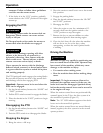
4. Raise and lock the deck to the 5 1/2 inch (14 cm)
transport position (
Figure 16).
The deck is raised by pushing the foot operated
deck lift pedal forward. The pedal is located at the
front right corner of the oor pan.
Note: When changing the cutting height
positions, always come to a complete stop
and disengage the PTO.
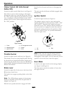
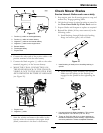
Figure 16
1. Deck foot pedal 3. Height of cut decal
2. Height adjustment pin 4. Transport lock control
5. Insert the height adjustment pin into the hole
corresponding to the desired cutting height.
See the decal on the side of the deck lift plate for
cut heights.
6. Push the deck lift pedal, release the transport lock
and allow the deck to lower to the cutting height.
Adjusting the Anti-Scalp Rollers
It is recommended to change the anti-scalp roller
position, when the height of cut has changed.
1. Stop the machine and move the motion control
levers outward to the neutral locked position.
2. Disengage the PTO.
3. Engage the park brake.
4. Stop the engine, remove the key and wait for all
moving parts to stop.
5. After adjusting the height of cut, adjust the
anti-scalp rollers by removing the nyloc nut,
bushing, spring disc washer and whizlock nut.
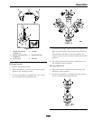
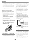
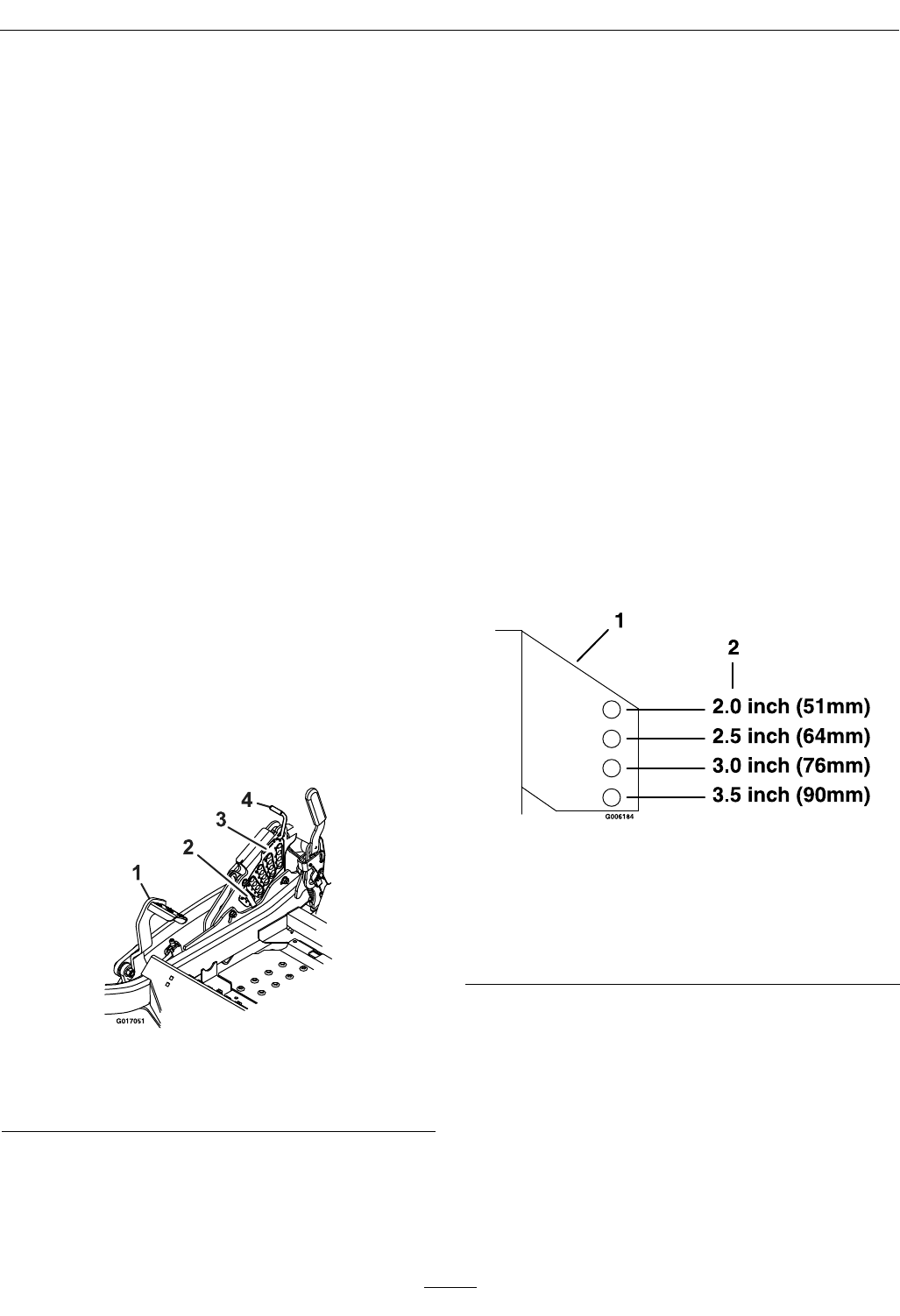
6. Place the rollers in one of the positions shown
(Figure 17). Rollers will maintain 3/4 inch (19
mm) clearance to the ground to minimize gouging
and roller wear or damage.
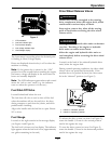
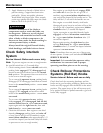
Figure 17
For cutting heights above 3.5 inches (90 mm) use the
bottom hole. The rollers will still be effective against
scalping.
1. Anti-scalp roller
mounting bracket
2. Cutting height
For Maximum Deck Flotation, place the rollers
one hole position lower. Rollers should maintain
1/4 inch (6.4 mm) clearance to the ground. Do
Not adjust the rollers to support the deck.
7. Be sure the whizlock nuts are installed with the
spring disc washer between the head of the nut
and the mounting bracket.
Note: The foot operated deck lift assist lever
can be used to momentarily lift the deck to clear
objects. Be sure that PTO is disengaged.
28