


Maintenance
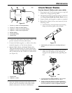
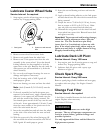
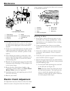
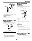
Figure 29
1. Single point height adjustment bolt
2. Front height-of-cut plate mounting bolt
3. Rear height-of-cut plate mounting bolt
15. To adjust the single point system, rst loosen the
front and rear height-of-cut plate mounting bolts.
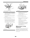
16. If the deck is too low, tighten the single point
adjustment bolt by rotating it clockwise. If
the deck is too high, loosen the single point
adjustment bolt by rotating it counterclockwise.
Note: Loosen or tighten the single point
adjustment bolt enough to move the height-of-cut
plate mounting bolts at least 1/3 the length of
the available travel in their slots. This will regain
some up and down adjustment on each of the
four deck links.
17. Re-tighten front and rear height-of-cut plate
mounting bolts.
Important: Torque the front and rear
height-of-cut plate mounting bolts to 27-33
ft-lb (37-45 N-m).
18. Repeat steps
9 through 13.
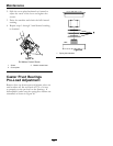
Pump Drive Belt Tension
Self-tensioning - No adjustment necessary.
Deck Belt Tension
Self-tensioning - No adjustment necessary.
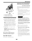
Adjusting the Parking Brake
Service Interval: After the rst 100 hours
Every 500 hours thereafter
Check to make sure brake is adjusted properly. This
procedure must be followed after the rst 100 hours
or when a brake component has been removed or
replaced.
1. Drive the machine onto a level surface.
2. Disengage the blade control switch (PTO), move
the motion control levers to the neutral locked
position and set the parking brake.
3. Stop the engine, wait for all moving parts to stop,
and remove the key.
4. Raise the back of the machine up and support the
machine with jack stands.
CAUTION
Raising the mower deck for service or
maintenance relying solely on mechanical
or hydraulic jacks could be dangerous. The
mechanical or hydraulic jacks may not be
enough support or may malfunction allowing
the unit to fall, which could cause injury.
Do Not rely solely on mechanical or hydraulic
jacks for support. Use adequate jack stands
or equivalent support.
5. Remove the rear tires from the machine.
6. Remove any debris from the brake area.
7. Rotate the drive wheel release handle to the
“released” position. Refer to the Drive Wheel
Release Valves section in Operation.
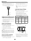
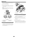
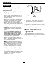
8. Measure the overall length of the compression
spring. The correct length should be between
1 1/2–1 9/16 inches (3.8–4.0 cm). If the spring
length is within this range, no adjustment is
needed. If it is not, proceed to step 9.
9. Hold the threaded rod end with a tool and adjust
the lock nut until the spring length is between
1 1/2–1 9/16 inches (3.8–4.0 cm) see Figure 30).
Do Not allow the cable to turn when the nuts are
being loosened.
41