


10
Tools Required: None
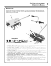
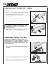
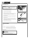
Parts Required: PAS or SRM-SB Power Head w/Shaft & Coupling.
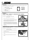
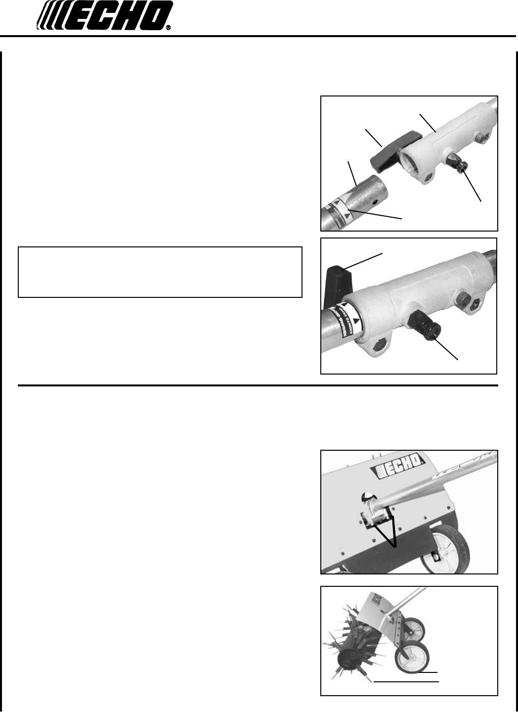
1. Set Power Head/Shaft Assembly on a level surface.
2. Pull locator pin (A) out, and turn counter-clockwise 1/4 turn to
lock-out position.
3. Remove vinyl cap from attachment drive shaft.
4. Carefully t attachment drive shaft assembly into coupler (B) to
decal assembly line (C), making sure that the inner lower drive
shaft engages into the square upper drive shaft socket.
NOTE
Earlier model Power Heads may have shorter couplings. Short
couplings t ush to decal point (E). New couplings are 4-3/4 in.
long, and t ush to line (C).
5. Rotate locator pin (A) 1/4 turn clockwise to engage lower shaft
hole. Insure locator pin is fully engaged by twisting lower drive
shaft. Locator pin should snap ush in coupler. Full engagement
will prevent further shaft rotation.
6. Secure lower shaft assembly to coupler by tightening clamping
knob (D).
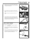
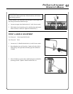
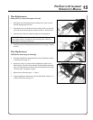
f e n d e r /w h e e l a s s e m b l y a d j u s t m e n t
Dethatcher combing efciency is best when the full weight of the
dethatcher assembly rests on the tines during operation. Wheel height
should be adjusted for 6 - 13 mm (0.25 - 0.50 in.) above ground for
operational stability over uneven grass. Perform wheel height adjust-
ment procedures as follows:
1. Loosen (2) two lower hex head wheel bracket bolts (B) with 4 mm
hex wrench.
2. Hold unit in comfortable operating position on a at surface and
check for wheel to ground clearance of 6 - 13 mm (0.25 - 0.50 in.).
3. Rotate wheels towards tines to reduce ground clearance; away
from tines to increase ground clearance. Tighten bolts (B).
p o w e r h e a d s h a f t t o l o w e r s h a f t a s s e m b l y
D
A
B
E
C
D
A
6 - 13 mm
(0.25-0.50 in.)
↔
B