


Dayton Operating Instructions and Parts Manual
9
Version B - For Reduction G016.J
®
Models 3WY47, 3W735B, 3W736C, 3WY44, 3TE27A,
3WY45, and 3WY46
0
1
0
0
2
0
0
3
0
F
F
U
E
L
0
100
200
30
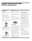
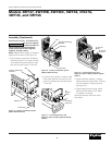
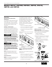
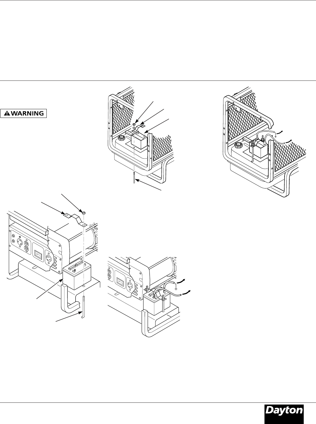
Battery Mounting
Bracket
Nut
Battery
Hook Bolt
Figure 15 – Battery Hold-Down System
(Model 3WY45 Shown)
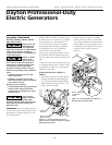
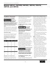
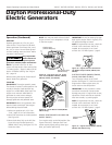
2. Locate the red, positive (+) battery cable
from starter solenoid. Connect it to the
positive (+) battery terminal (See Figures
17 and 18).
Figure 17 – Connecting Positive and
Negative Cables to Battery (Model 3WY45
Shown)
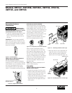
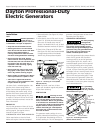
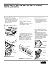
Figure 16 – Battery Hold-Down System
(Model 3WY47 Shown)
Battery
Hook Bolt
Battery Mounting
Bracket
Nut
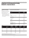
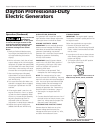
Figure 18 – Connecting Positive and
Negative Cables to Battery (Model 3WY47
Shown)
F
F
U
E
L
3. Locate the black, negative (–) battery
cable attached to engine block. Connect
it to the negative (–) battery terminal
(See Figure 16).
4. Check battery before starting engine.
Make sure fluid levels are full. Make
sure battery is charged.
See engine owner’s manual for more
information.
To Engine
Block
To Starter
Solenoid
MOUNTING BATTERY TO GENERATOR
Do not over tighten
positive terminal on
starter solenoid. Positive terminal
could rotate and cut into negative
terminal, causing a short.
NOTE: Model 3WY47 battery is located on
opposite side as shown (See Figure 16).
1. Secure battery to generator by battery
hold-down system. This system consists
of the battery mounting bracket, hook
bolt, and nut (See Figures 15 and 16).
Assembly (Continued)
To
Engine
Block
To Starter
Solenoid