


Dayton Operating Instructions and Parts Manual 3WY47, 3W735B, 3W736C, 3WY44, 3TE27A, 3WY45, and 3WY46
16
Dayton Professional-Duty
Electric Generators
®
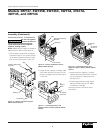
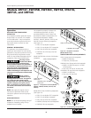
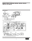
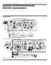
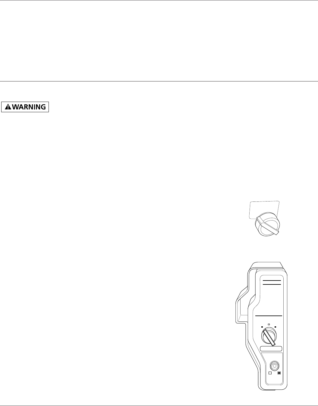
Figure 34 – Engine Switch in OFF Position,
Models 3WY46, 3WY45, and 3WY47
HONDA
OFF
ON
START
ENGINE SW
CIRCUIT
BREAKER
ON/push OFF
OFF
ENGINE SW
ON
Figure 33 – Engine Switch In OFF Position, All
Models Except 3WY46, 3WY45, and 3WY47
Operation (Continued)
HIGH ALTITUDE OPERATION
This generator will not perform well at
high altitudes without proper adjustment.
See engine owner’s manual for details.
ADDING ELECTRICAL LOADS
IMPORTANT: Do not overload generator.
Make sure total wattage of all electrical
loads does not exceed rated wattage of
generator. Overloading may shorten
generator life. It could also cause internal
damage to generator. Overloading
will trip circuit breaker.
IMPORTANT: Keep full power selector
switch in the 120 VOLT ONLY position if
only powering 120V items. Only move
switch to 120/240 VOLT position if
powering 240V items.
1. Check items to be powered. Their
nameplate lists their wattage ratings.
NOTE: The wattage ratings for some
electrical motors are misleading. They may
require 3 to 6 times their rated wattage to
start. You must figure total electrical load
wattage. Make sure total wattage of all
electrical loads does not exceed rated
wattage of generator. See “Determining
Electrical Load for Generator,” page 11.
2. Start engine. Let engine reach full
speed.
3. Connect electrical loads one at a time. If
the load consists of electric motors, start
them first. Always start the largest first.
Start each motor individually.
DISCONNECTING ELECTRIC LOADS
Remove electrical loads one at a time.
Remove voltage sensitive items first.
Voltage sensitive items include TVs, VCRs,
and other home electronic items.
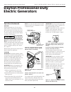
STOPPING ENGINE
IMPORTANT: The engine speed is preset.
The throttle is locked in preset position. Do
not adjust throttle.
Follow the steps below to stop engine.
1. Remove all electrical loads from
generator (See “Disconnecting Electrical
Loads,” above). Remove electrical loads
one at a time.
2. Let engine run for two or three minutes
after removing electrical loads. This lets
engine cool slightly.
3. Turn engine switch to the OFF position
(See Figures 33 and 34).
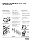
Always set the idle
speed before
turning on the auto-idle. If idle speed
is not set, the larger resistor on the
control board may become hot. Heat
from the resistor may damage the
protective coating on the control
board.
5. Slowly pull solenoid bracket away
from engine (on Model 3WY47 this
will require bending the bracket
slightly).
6. With a volt meter, check the no-load
output voltage at the 120-volt duplex
receptacle. At proper idle speed (2680
minimum RPM) the meter should read
50-60 volts. Lower settings will cause
the auto-idle to not operate properly.
7. After reaching proper idle speed,
tighten M8 nut to secure solenoid
mounting bracket (Models 3WY46
and 3WY45 only).
8. Turn auto-idle switch ON. Make sure
solenoid is engaged. When engaged,
the plunger is pulled back into the
solenoid.
9. If the engine speed is too slow, the
engine will want to "hunt" or speed
up and slow down repeatedly. When
this occurs, increase engine speed by
adjusting throttle stop screw on
carburetor (refer to Carburetor
Adjustment in Honda Engine Manual).
10. Replace the engine linkage cover
(Models 3WY46 and 3WY45 only).