


Dayton Operating Instructions and Parts Manual
37
Version B - For Reduction G016.J
®
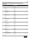
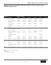
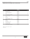
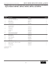
Reference
Number Description Part No. Quantity
1 Control board assembly 100105-01 1
2 10-32 x 3/4" Hex head screw 26499000 4
3 Nylon spacer 100321-01 4
4 #10 Flat washer WP-3C 4
5 10-32 Lock nut 26514000 4
6 Solenoid assembly (includes plunger, nut, 100324-03 1
and lock washer)
7 Retaining ring* 103812-01 1
8 Linkage rod 100755-01 1
Linkage rod* 100755-02 1
9 Roll pin 22822000 1
10 Solenoid mounting bracket* 102939-01 1
Solenoid mounting bracket 100756-01 1
11 Nylon washer* 103811-01 1
12 M8 x 25mm Bolt 100328-01 1
13 5/16" Flat washer 02407002 1
14 M8 Lock nut 100329-01 1
∆ Yellow wire 100320-01 1
∆ White wire (with 2 flags) 100322-01 1
∆ White wire (with 1 flag and 1 spade) 100322-02 1
∆ Rocker switch 100366-01 1
∆ Auto-idle decal 100334-01 1
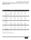
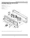
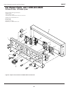
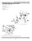
Repair Parts List for Solenoid and Control Board Assemblies and Mount-
ing for Models 3W736C, 3WY44, 3TE27A, 3WY45, and 3WY46
(*) Model 3WY47 only.
(∆) Not shown.
3WY47, 3W736C, 3WY44, 3TE27A, 3WY45, and 3WY46