


Dayton Operating Instructions and Parts Manual 3WY47, 3W735B, 3W736C, 3WY44, 3TE27A, 3WY45, and 3WY46
6
Dayton Professional-Duty
Electric Generators
®
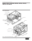
Generator Features
(Continued)
from the oil level sensing device. This will
cause the oil alert system to shut down
engine.
See engine owner’s manual for more
information.
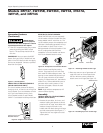
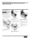
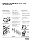
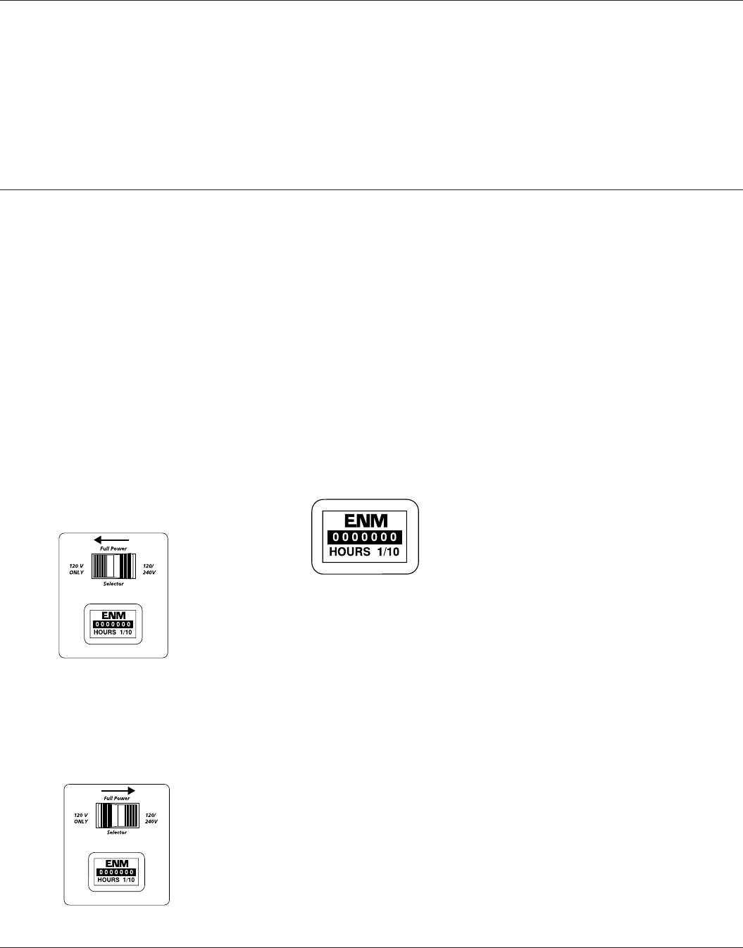
FULL POWER SELECTOR SWITCH
All models except 3W735B, 3WY47, and
3WY45 have a full power selector switch
on the control panel. The switch has two
positions: 120 VOLT ONLY, and 120/240
VOLT.
120 VOLT ONLY: This position sends full
power to the 120V receptacles only. 240V
power is not available. Use this position
when powering 120V items only.
Figure 5 – Full Power Selector Switch in 120
Volt Only Position
120/240 VOLT: This position sends full
power to the 120/240V receptacle. It also
powers the 120V receptacles at reduced
wattage capacity.
Figure 6 – Full Power Selector Switch in
120/240 Volt Position
IMPORTANT: Do not move the full power
selector switch while powering electrical
items. Unplug all items before moving
switch. Failure to do so can damage
switch.
Models 3W735B, 3WY45, and 3WY47 do
not have this switch. These models provide
full power to all receptacles.
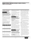
HOUR METER
All models except 3W735B have an hour
meter. The hour meter is on the control
panel. The hour meter shows the total
generator run time, including all idle time
(See Figure 7). Hour meter is accurate up
to 1/10 of an hour.
AUTO-IDLE SYSTEM
The auto-idle system allows the engine to
idle down or run at a slower speed when
the generator is not being used to supply
power. The auto-idle system can be turned
ON or OFF by a rocker switch on the
control panel. When the switch is in the
OFF position, the engine runs at full speed
all of the time. When the switch is in the
ON position, the engine slows down to
idle speed until an electrical load is
applied. When a load is applied to the
generator (an electrical item is plugged in
and turned on) the engine speeds up to
the preset speed required to produce the
correct voltage.
IMPORTANT: A minimum current load of
1 Amp is required to disengage the auto
idle solenoid and cause the engine to
come up to speed for correct voltage.
Figure 7 – Hour Meter
GROUND FAULT CIRCUIT INTER-
RUPTER RECEPTACLE
All models have a 120-volt ground fault
circuit interrupter (GFCI) receptacle. The
GFCI receptacle is on the control panel or
top cover of alternator (Model 3W735B
only). The GFCI protects you against
hazardous electrical shock caused when
your body becomes a path through which
electricity travels to reach ground. This
could happen when you touch an appli-
ance or cord that is ‘live’ through faulty
mechanism, damp or worn insulation, etc.
When protected by the GFCI, you may still
feel a shock, but the GFCI should cut it off
quickly. A person in normal health should
not receive serious injury.
NOTE: Infants and very small children may
still be affected.
TEST PROCEDURE
Check the GFCI receptacle every month.
This insures it is working right.
1. Push black TEST button. Red RESET
button should pop out. This should trip
GFCI, resulting in no electrical power at
receptacle. Verify this by plugging test
lamp with good bulb into receptacle. If
lamp does not work, GFCI receptacle is
good.
Powering items at reduced engine speed
will damage generator and powered
items.
ELECTRIC START (MODELS 3WY46,
3WY45, AND 3WY47 ONLY)
Models 3WY46, 3WY45, and 3WY47 have
an electric starter. A battery is not supplied
with generator. You must provide a 12-
volt, 32-amp-hour battery. For more
battery information, see “Battery,” page 8.