


22
available from any auto supply store. Follow
the directions on the can. If the leaks are
larger than 1/16" diameter, the tire can be
repaired with rubber plugs also available in a
kit from any auto supply store. If the tire bead
is damaged, a tube will have to be installed in
the tire or the tire will have to be replaced.
3.
Creeping:
Creeping is the slight forward or
backward movement of the mower when the
throttle is on and the lapbars are in the neutral
position. If your mower creeps, refer to Steer
-
ing Lever Adjustment Section F4, page 23.
E. Brakes
While the mower is in motion, all braking is performed
dynamically through the hydraulic pumps and traction
motors, controlled by the two steering levers. When the
mower is stationary with the engine running, the
hydraulic system locks the traction wheels. If the engine
is shut off, the park brake should be engaged.
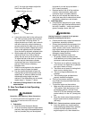
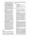
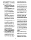
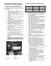
Note: To move the mower forward or in
reverse by pushing, you must release the
dynamic braking. Locate the valves on the
pump. Turn valves counter-clockwise (using a
standard 7/16” wrench) one quarter turn to push
the unit. After pushing the mower to the desired
location, return both valves to the operating
position by turning the valve clockwise, but do
not overtighten(See photo below)
.
When the mower is parked with the engine running
and the steering levers in the neutral position, the
parking brakes should be applied. The parking brakes
are drum-type brakes mounted on each traction
wheel. They are both engaged by the same operating
lever.
1.
Adjustments:
The parking brake handle is an
overcenter lever that should engage with
moderate force.
Note: To increase parking brake capacity,
adjust brake cables at the brake arms equally.
Adjust the cable housing nuts one full turn
and check parking capacity. Repeat if parking
brake does not hold.
2.
Repair:
The mower is equipped with drum
brakes and will not normally require mainte
-
nance. If they are not working properly, please
contact your service center.
F. Hydraulic System
WARNING:
Never overfill the hydraulic units. Damage can
occur if the oil level is not within the proper
operating range.
Note: When adding hydraulic oil, do so in
small quantities and recheck the oil level
before adding more. It is important that you do
not overfill the reservoir to allow for fluid
expansion.
1.
Hoses:
Check the hoses from the hydraulic
oil tank to the oil filter to the hydraulic lines
daily for leaks or abrasion and replace any
damaged hoses. Make certain there are no
kinks or twists in any hose.
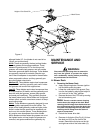
2.
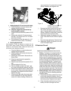
Hydraulic Oil Tank and Filter:
Note: Change the hydraulic oil and the oil
filter element after the first 50 hours of opera-
tion and every 500 hours thereafter.
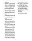
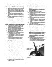
To drain the hydraulic oil tank, place a 1 gallon drain
pan under the drain plug on the bottom of the
hydraulic oil tank. Remove the drain plug, drain the
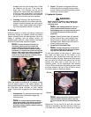
tank, then replace the plug. Remove the three screws
from the top of the oil filter and take out the oil filter
element You don’t have to drain the rest of the
hydraulic system. Put the replacement filter element
in the oil filter and lubricate the sealing surface. Install
the three screws in the top of the oil filter to secure
the oil filter element. (See photo below)
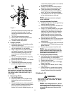
Note: Always wipe off the hydraulic tank fill
cap and the area around it before removing
the cap to prevent dirt from contaminating the
oil.
Remove the fill cap and fill the tank with the same
15W-40 oil selected for the filter until the oil level is a
1/4” below the oil tank fill neck. Leave this air space
Left Side Pump
Bypass
Valve
Screw
Screw