


21
when slight contact with the feeler gage
occurs. Engage the BBC (PTO Clutch) a
couple of times, and re-check the air-gap.
If it is not between the specs listed on page
22, repeat the adjustment procedure.
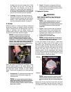
b. Steering lever/Parking Brake Switch: Sit
in the operator’s seat. With both steering
levers in the neutral position and the blade
clutch switch “off”, release the parking
brake and try to start the engine. The
engine should not start. If it does, the park
-
ing brake switch must be repositioned or
perhaps replaced. If the engine does not
start, engage the parking brake and start
the engine.
c. Seat Switch: With both steering levers in
the neutral position, the parking brake
engaged and the blade clutch switch in the
“off” position, start the engine. Now
release the parking brake, hold down on
the back of the operator’s seat against
spring pressure. Release the operator’s
seat and the engine should stop. If the
engine does not stop, the seat switch must
be replaced. With both steering levers in
the neutral position, the parking brake
engaged and the blade clutch switch in the
“off” position, sit in the operator’s seat and
start the engine. Turn the blade clutch
switch to the “on” position and the blades
should start to rotate. Raise up slightly off
the operator’s seat and the blades should
stop. If the blades do not stop when you
dismount from the operator’s seat, the seat
switch must be replaced.
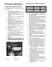
d. Electric PTO Clutch: This clutch operates
when the engine is running, the operator is
in the operator’s seat and the blade clutch
switch is turned on.This electric clutch is a
fairly trouble free device. If a problem
develops and the blades do not turn, first
check the 20 amp fuse in the yellow, 16-
gauge wire between terminal “L” (for the
Gasoline Engine) on the ignition switch
and the hour meter and then investigate
the wiring harness and the connections to
the seat switch, the blade clutch switch and
the electric blade clutch. Then check out
the seat switch, the blade clutch switch and
finally the electric blade clutch.
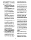
D.Tires
The two front wheels are caster wheels that are free
to swivel to accommodate the direction of the Mower.
The two rear wheels are used to propel the Mower in
the direction of input from the drive handles. Inflation
pressure of the rear tires is important for stability
while the Mower is in operation. If the tire diameter is
not equal between the two tires, the Mower will pull to
one side.
1.
Inflation Pressure:
a. Traction Tires—20 psi max; 8-10 psi rec-
ommended
b. Front Caster Wheel—28 psi max; 20-25
psi recommended
c. Cutting Deck Ball Wheels—Solid Polyure-
thane.
Use the Following guidelines for maintaining the tires:
a. Balance inflation pressure between the
rear tires to help maintain straight travel
(see tire side wall for proper inflation pres
-
sure).
b. Keep the valve caps tightened to prevent
air pressure loss.
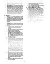
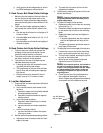
2.
Leaking Tires:
When a flat tire occurs, repair
or replace immediately. The normal procedure
is to remove the wheel and replace it with a
spare. Take the leaking tire to a maintenance
area and repair. If a tire is getting soft, park
the mower on the nearest level, paved area. If
the leaking tire is on a traction wheel, put
blocks on each side of the opposite traction
wheel and jack up the tire that leaks about an
inch off the ground. Loosen and remove the
lug nuts and remove the wheel. Mount a
spare wheel and tire, replace the lug nuts, and
using a torque wrench, tighten them to 60
±
10 ft-lbs.
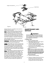
If the leaking tire is on a front caster wheel,
block both traction wheels and raise the
caster wheel so that the tire is an inch off the
ground. Loosen and remove the locknut from
the axle assembly and pull the axle assembly
from the caster yoke. The wheel and two
spacer sleeves will drop free. Slip the axle
assembly through one side of the caster
yoke, through a spacer sleeve, a spare
wheel, the other spacer sleeve and finally
through the other side of the caster yoke.
Then tighten the locknut on the end of the
axle assembly.
Lower the mower off the jack and continue
mowing. The wheel with the leaking tire
should be taken to the maintenance area, the
tire inflated to 20 psi and the wheel placed in
a large bucket of water. Carefully inspect the
tire, rim and valve for escaping air bubbles
which indicate a leak. Mark each leak with a
yellow marking crayon and then deflate the
tire to 8 psi and repeat the inspection. If the
leaks you find are pin hole size to 1/16"
diameter, the tire can be repaired using an
aerosol can of tire inflater and latex sealer