


20
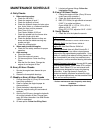
c. Store the battery with a full charge. A dis-
charged battery will freeze (refer to the
table below).
d. Recharge battery when ever the specific
gravity value is less than 1.225
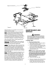
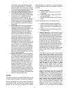
3. Battery Removal
Warning:
When removing the cables from the battery
follow these steps to avoid a short between
the wrench and the frame.
a. Remove the Negative (black) cable.
b. Remove the Positive (red) cable.
c. Release the hold down straps.
d. Remove the battery without tipping.
4. Installing the Battery
Note: The battery is delivered from the fac-
tory fully charged and filled with electrolyte.
a. Attach the Positive (red) cable.
b. Attach the Negative (black) cable.
c. Attach the rubber battery strap.
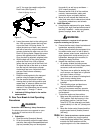
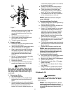
5. Jump Starting
Warning:
Note: For E.F.I. Tanks, the battery must be
disconnected (Negative lead) for storage
exceeding four weeks. Do not “Jump Start” an
E.F.I. unit, recharge or replace battery to avoid
damage to the Electronic Control Unit (ECU).
Failure to use this starting procedure can
cause sparking, and the gases in the battery
to explode.
a. Attach the end of the red jumper cable to
the Positive terminal (+) of the charged
battery.
b. Attach the other end of the red jumper
cable to the Positive terminal (+) of the low
charge battery.
c. Attach the end of the black jumper cable to
the Negative terminal of the charged bat
-
tery.
d. Attach the other end of the black jumper
cable to the frame of the unit with the low
charge battery.
6.
Fuses:
There is one fuse located in the wiring
between the ignition and start switch and
other electrical components. This is a stan
-
dard plug-in type automotive fuse rated at 7.5
amp.
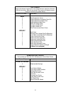
7.
Safety Switches:
There are three safety
switches in the electrical circuit which control
the engine. They are (1) the blade clutch
switch, (2) the steering lever/parking brake
switch, and (3) the seat switch.They operate
so that in order to start the engine, the blade
clutch switch must be off, the parking brake
must be engaged, and both steering levers
must be in the neutral position. Once the
engine is started, the seat must be occupied
and the parking brake must be released
before either of the steering levers can be
moved. Also, the seat must be occupied
before the blade clutch switch can cause the
blades to rotate.
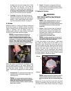
8.
Safety Switch Operation Checks:
The fol-
lowing operational checks should be made
daily.
a. Blade Clutch Switch: Sit in the operator’s
seat. With both steering levers in the neu
-
tral position and the parking brake
engaged, turn the blade clutch switch “on”
and try to start the engine. The engine
should not start. If it does, the blade clutch
switch must be replaced. If the engine
does not start, turn the blade clutch switch
“off” and start the engine. Now turn the
blade clutch switch “on” and the blades
should rotate. If the blades do not turn, the
blade clutch switch must be replaced, the
seat switch must be replaced or the elec
-
tric PTO clutch must be repaired.
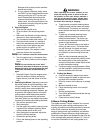
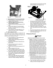
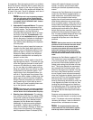
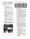
The air-gap should be checked every 100
hrs. (or less, if severe operating conditions
exist such as when there are many on/off
cycles, mulching operations, material col
-
lection systems used, and dusty/dirty con-
ditions), and the air-gap adjusted if more
than 0.025". To inspect, remove the “nega
-
tive” cable from the battery and all spark-
plug wires. The air-gap should be checked
with feeler gages in the three slots of the
BBC (PTO Clutch). See page 22 for air gap
adjustment specs. There are three inspec
-
tion slots in the brake cover. To adjust, suc-
cessively tighten each of the three gap
adjustment nuts an equal amount. Insert a
feeler gage (see page 22 for specs) into
each slot as the air gap adjustment nut are
tightened. The correct adjustment occurs
Specific Gravity Freezing Temp (°F)
1.265 -71
1.250 -62
1.200 -16
1.150 5
1.100 16