


41
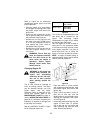
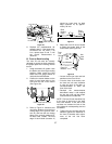
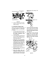
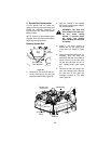
Figure 40
9. From the left side of the tractor,
slide the mower deck out from
under the tractor.
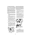
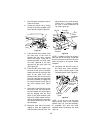
B. Installation of Mower Deck
NOTE: The LH lift link must be raised
to provide clearance for sliding the
mower deck under, or out from under,
the tractor.
1. To ensure the tractor lift links can
be fully lowered, lower the deck
downstop by continuously turning
the height adjustment knob
counterclockwise
2. If not already done, lock the LH lift
link in its deck installation/removal
position as follows: (Refer to Fig-
ures 37A through 37D).
• Holding the LH lift rod downward,
lift upward on the release tab of the
lift stop bracket while raising the
rearward end of the lift link to align
its slot with the notch of the LH lift
rod (See Figures 37A and 37B).
• Swing the LH lift rod forward until
fully to the front of the lift link slot
(See Figures 37C and 37D).
3. Start the tractor and use the
hydraulic lift to fully raise the left
lift link. Stop engine.
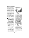
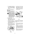
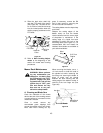
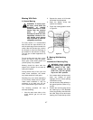
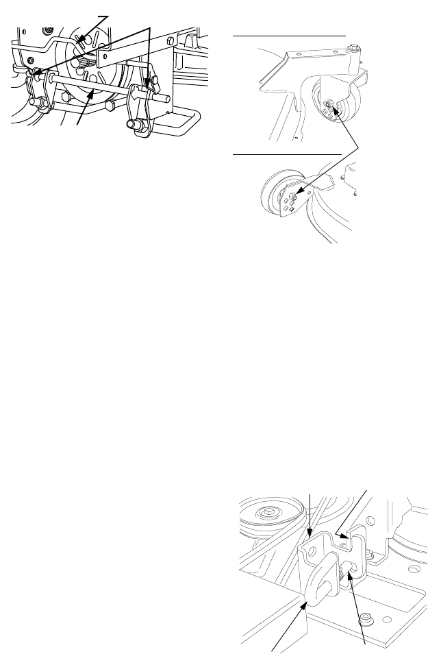
4. Check the caster wheel and
gauge wheel settings on the deck.
If necessary, remove the hex cap
screws and nylon lock nuts, and
adjust the wheels to their highest
setting (lowest deck setting). See
Figure 41.
Figure 41
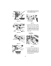
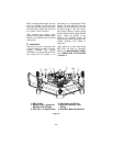
5. From the left side of the tractor,
slide the deck under the tractor
until the slots of the LH and RH
rear deck brackets align approxi-
mately with the tractor lift links
(See Figure 42).
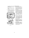
6. Pull outward and cock the deck
support pins in the rear deck
brackets so that both spring-
loaded pins are held in the disen-
gaged position against the inner
surface of the deck brackets
(See Figure 42).
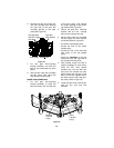
Figure 42
Latch Receiver
Slots
Front Lift
Bracket/Rod Ass’y.
Quick Latch Rod
Front Caster Wheel
Rear Gauge Wheel
Upper Hole
Slot
Rear Deck
Bracket
Deck
Support Pin
Pin Locked in
Disengaged
Position