40
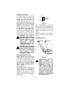
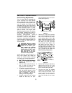
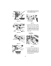
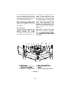
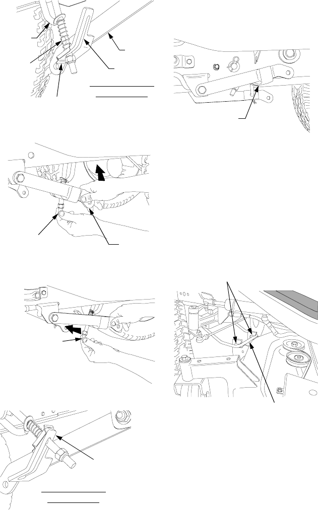
Figure 37A
Figure 37B
Figure 37C
Figure 37D
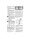
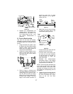
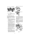
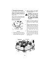
6. Use the hydraulic lift to fully raise
the LH and RH lift links (See Fig-
ure 38). Stop the engine.
Figure 38
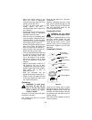
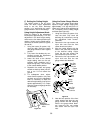
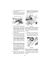
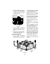
7. Roll the deck forward to disen-
gage the front lift rod from the
slots of the front roller bracket
(See Figure 39). Hold the front lift
rod upward and slide the deck
rearward until the lift rod rests on
top of the roller bracket, forward
of the slots.
Figure 39
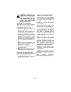
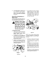
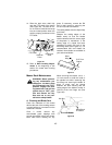
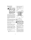
8. From the front of the tractor, pull
the center of the quick latch rod
downward to release the front lift
bracket/rod assembly. Slide the
front lift bracket assembly from
the latch receiver slots of the trac-
tor (See Figure 40).
LH Lift
Link
Slot
Lift Stop Bracket
Release Tab
LH Lift
Rod
Notch
VIEWED FROM
RIGHT SIDE
Lift
Upward
Hold
Down
Swing Lift
Rod Forward
LH Lift Link
Locked
VIEWED FROM
RIGHT SIDE
Left Lift Link
Fully Raised
Front Lift Rod
Front Roller
Bracket Slots


