


39
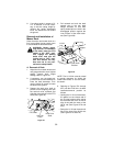
6. If a cutting height in excess of 3-
1/2” is desired, it will be neces-
sary to set the cutting height by
utilizing the height adjustment
knob. The wheels will not contact
the ground.
Removal and Installation of
Mower Deck
Place the tractor and mower deck on a
firm, level surface having enough room
to accomodate the deck and tractor.
WARNING: Before begin-
ning removal, or installation
of the deck, place the PTO
switch in the “OFF” posi-
tion, engage the parking
brake lever, and turn the
ignition key to “OFF” posi-
tion and remove the key.
Use care not to cut your-
self on the sharp blades.
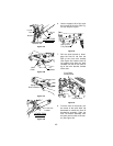
A. Removal of Deck
1. Adjust the front caster wheels and
rear gauge wheels to their highest
setting (lowest deck height
setting). Refer to Figure 34.
2. If necessary, turn the height ad-
jusment knob counterclockwise to
lower the deck downstop. Then
use the tractor lift system to lower
the deck to the ground.
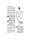
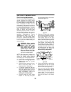
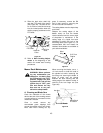
3. Support the deck drive shaft to
prevent it from dropping; then pull
the auto-lok collar rearward and
slide the drive shaft off of the PTO
shaft (See Figure 35).
Figure 35
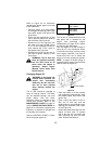
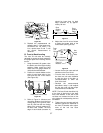
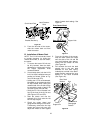
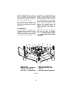
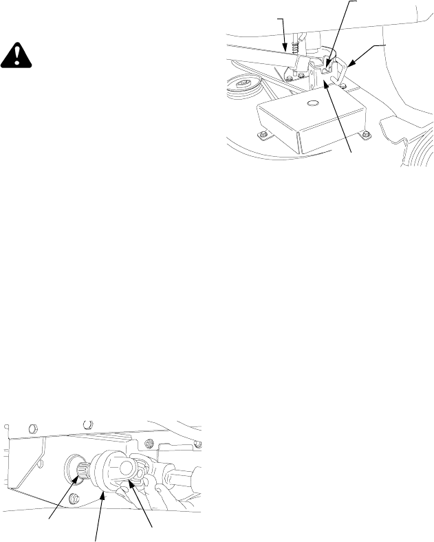
4. Pull outward and cock the deck
support pins in the rear deck
hanger brackets so that both
spring-loaded pins are held in the
disengaged position against the
inner surface of the deck brack-
ets (See Figure 36).
Figure 36
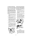
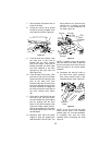
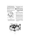
NOTE: The LH lift link must be raised
to provide clearance for sliding the
mower deck under, or out from under,
the tractor.
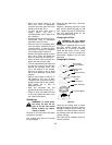
5. Refering to Figures 37A through
37D, lock the LH lift link in its deck
installation/removal position as
follows:
• Holding the LH lift rod downward,
lift upward on the release tab of
the lift stop bracket while raising
the rearward end of the lift link to
align its slot with the notch of the
LH lift rod (See Figures 37A and
37B).
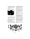
• Swing the LH lift rod forward until
fully to the front of the lift link slot
(See Figures 37C and 37D).
Deck Drive
Shaft
Auto-Lok
Collar
PTO Shaft
Inner Hole
Deck
Support
Pin
LH Lift
Link
Rear Deck
Bracket