


38
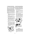
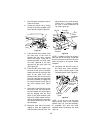
C. Setting the Cutting Height
The cutting height is set by using
either the deck height adjustment
knob to set the deck downstop
position or by positioning the caster/
gauge wheels in one of five settings.
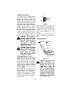
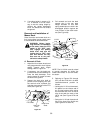
Using Height Adjustment Knob
Each full rotation of the adjustment
knob equals approximately a 1/4 inch
adjustment in the deck height setting,
and there are four detent positions per
rotation. Initially set the height adjust-
ment knob as follows (Refer to Figures
33 and 34):
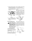
1. Using the tractor lift system, fully
raise the deck. Raise the caster
and gauge wheels to their highest
position.
2. Fully lower the deckstop by con-
tinuously turning the adjustment
knob counterclockwise.
3. Lower the deck to the desired
height setting, then turn the ad-
justment knob clockwise until it
stops turning freely. Turn the knob
to the nearest detent position.
4. Reposition the caster and gauge
wheels so that they either just con-
tact or are 1/2 inch above the
ground.
5. For subsequent minor adjust-
ments from this position, fully raise
the deck and turn the adjustment
knob as necessary to attain the
desired height setting (one full turn
equals approximately 1/4"). Repo-
sition the caster and gauge wheels
as necessary.
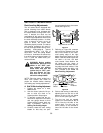
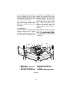
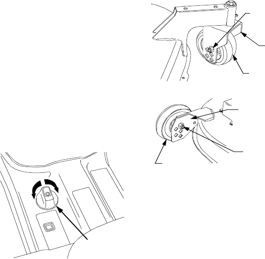
Figure 33
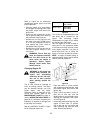
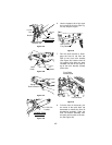
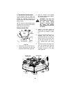
Using the Caster/Gauge Wheels
The holes in the caster wheel yokes
equate to height settings ranging from
approximately 1-1/2” (top hole) to 3-1/2”
(lower hole), with the holes positioned at
1/2” increments. Set the cutting height
as follows (See Figure 34):
1. Using the tractor lift system, fully
raise the deck. Fully lower the
deckstop by continuously turning
the adjustment knob counter-
clockwise.
2. Remove the hex cap screws and
nylon lock nuts from the front
caster wheels and yokes .
3. Align the caster wheels with the
holes in the yoke that correspond
to the desired cutting height.
Insert the hex cap screws and
secure with the nylon lock nuts.
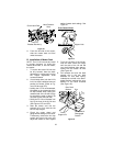
4. Remove the hex cap screws and
nylon lock nuts from the rear
gauge wheels and brackets.
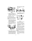
Figure 34
5. Note the hole position of the front
caster wheels and align the rear
gauge wheels with the matching
holes in the gauge wheel brack-
ets. Insert the hex cap screws
and secure with the nylon lock
nuts.
RAISE
LOWER
Height
Adjustment
Knob
Caster
Wheel
Yo k e
Lock Nut
Front
Caster
Wheel
Gauge
Wheel
Bracket
Hex Cap
Screw &
Rear
Gauge
Wheel
Hex Cap
Screw &
Lock Nut