


20
• Release the Parking Brake Lever. If
the tractor cannot be pushed
forward or rearward, the braking
force must be decreased.
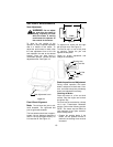
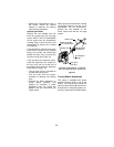
Adjusting the Brake.
Remove the rear drawbar from the
frame by removing the four hex tapp
screws. NOTE: The oil fill tube/dipstick
will be pulled from the transmission
housing. Plug or cover the hole in the
transmission to prevent dirt or debris
from entering.
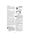
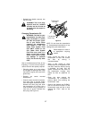
From beneath the right/rear side of the
tractor frame, secure the hex shaped
flange of the brake rod (located just
behind the brake link) to prevent the
rod from turning (See Figure 15).
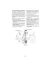
From just above the right axle carrier,
inside the right frame rail, slowly turn
the hex nylon lock nut at the end of
the brake rod as follows to adjust the
brake (Refer to Figure 15):
• Turn the nylon lock nut clockwise to
increase the braking force.
• Turn the nylon lock nut counter-
clockwise to decrease the braking
force.
• Recheck the brake adjustment to
ensure proper operation, and
readjust as necessary. If brake
adjustment does not correct the
problem, see your authorized Cub
Cadet dealer.
While guiding the transmission release
rod through keyhole and the oil fill
tube/dipstick into the transmission,
position the rear drawbar on the
frame. Secure with the four hex tapp
screws.
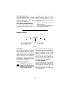
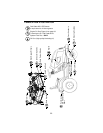
Figure 15
Turning Radius Adjustment
This tractor is equipped with power
assisted steering which is set at the
factory. The turning radius should be
equal for both left and right hand turns.
If adjustment is necessary please con-
tact your authorized Cub Cadet dealer.
Brake Link
Brake Rod
Brake Shaft
Hex Shaped
Flange
Assembly
Brake Assembly
(On Transmission)
VIEWED FROM ABOVE - FENDER
AND RUNNING BOARD REMOVED
Hex Nylon
Lock Nut