


42
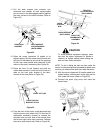
8. Raise the deck to the highest position. Recheck
the blade measurements described in step 4. If the
resultant measurements are not correct, repeat
steps 5, 6 and 7 until the proper measurements are
obtained.
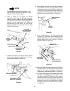
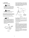
NOTE
The front lift rod should be against the front of
both slots in the deck front roller bracket. If one
side of the rod is not against the front of the slot
after attaining the correct front pitch to the deck,
tighten the front lock nut on that side until the
rod just contacts the front of the slot.
9. Tighten the rear jam nuts after adjustment of the
front lift rod is completed.
10. Connect the spark plug wires if previously
disconnected.
CUTTING HEIGHT ADJUSTMENT
WARNING
Before making any adjustments, place the PTO
switch in the “OFF” position, engage the brake
pedal lock, turn the ignition key to the “OFF”
position and remove the key from the switch.
WARNING
When adjusting the mower deck, be careful not
to cut yourself on the sharp blades.
NOTE
Cutting height adjustment should be performed
only AFTER the mower deck has been properly
leveled. Place the tractor on a firm, level surface
and check for proper tire inflation.
When using the 48" mower deck, all four ball wheels
should contact the ground. Therefore the cutting height
is adjusted by raising or lowering the ball wheels.
When adjusting the cutting height take note of the
following:
• The highest holes in the index spindle for
the front ball wheels correspond to the low-
est cutting height for the mower deck.
• The lowest holes in the index spindle for the
rear ball wheels correspond to the lowest
cutting height for the mower deck.
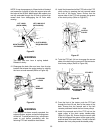
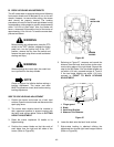
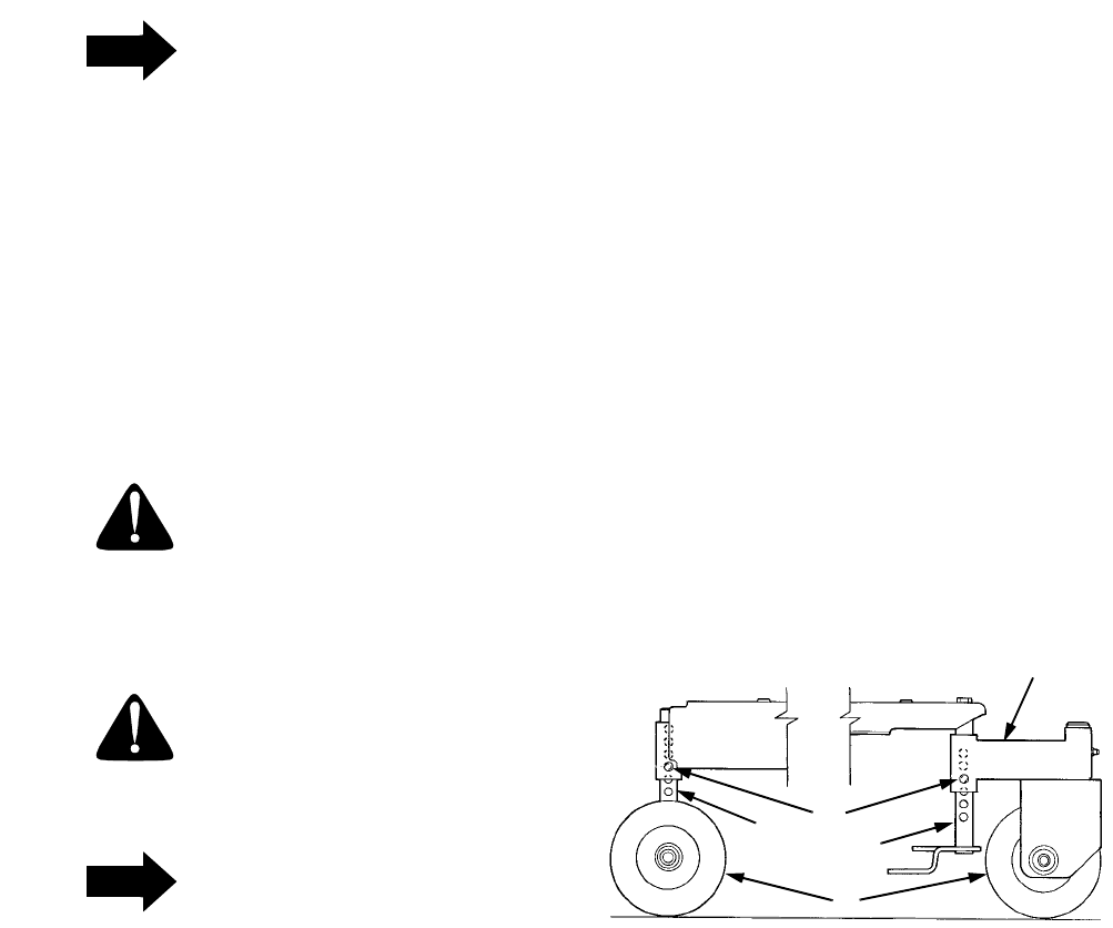
To adjust the mower deck cutting height by raising or
lowering the ball wheels, refer to Figure 62 and
proceed as follows:
1. Move the tractor implement lift handle to the
position that places the ball wheels slightly above
or just contacting the surface below.
2. Remove the quick release pins from both the rear
ball wheel spindles and the front ball wheel caster
assemblies.
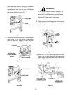
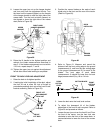
3. As necessary, raise or lower the tractor
implement lift handle to place the mower deck at
the desired cutting height.
4. Position the front castor brackets to align with the
hole in the index spindles that allow the ball
wheels to just contact the surface below.
Reinstall the quick release pins to secure the
castor brackets. Both castor brackets should be
pinned in the same index spindle hole location.
5. Note the index spindle hole used for the front
castor brackets and adjust the rear ball wheels to
the corresponding hole in the rear index spindle.
Remember the lowest index hole in the rear
spindle corresponds to the highest index hole in
the front castor spindle. All four ball wheels
should be installed using the same relative index
hole location in each spindle.
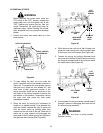
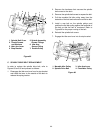
Figure 62
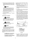
6. The correct mower deck cutting height
adjustment is achieved when the tractor
implement lift handle is lowered to the desired
mower deck cutting height and all four mower
deck ball wheels just contact the surface below.
1
2
3
4
5
1. Ball Wheel
2. Front Castor Bracket
3. Quick Release Pin
4. Front Index Spindle
5. Rear Index Spindle