


35
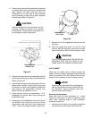
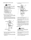
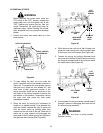
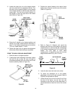
NOTE: It may be necessary to lift each side of the deck
and maneuver it slightly to align the support pins with
the holes of the lift links. Make certain the support pins
are fully extended through the lift links to prevent the
mower deck from disengaging the lift links while
mowing.
Figure 35
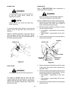
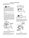
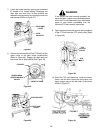
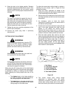
WARNING
The deck idler arm lever is spring loaded.
Release it slowly.
12. Disengage the deck idler arm lever from its stop
bracket and release the spring tension by rotating
the lever out and rearward (Refer to Figure 36).
Figure 36
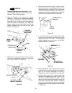
WARNING
If the engine has been recently operated, the
exhaust system, engine, and surrounding areas
will be hot. To avoid personal injury, allow these
areas to cool before proceeding with the
following PTO belt installation instructions.
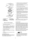
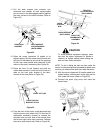
13. Install the forward end of the PTO belt on the PTO
clutch pulley by passing the belt upward inside
the front of the tractor frame. Ensure that the
narrow side of the PTO belt engages the groove
of the clutch pulley (Refer to Figure 37).
Figure 37
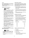
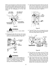
14. Twist the PTO belt 1/4 turn to engage the narrow
sides of the belt into the grooves of the two tractor
front-lower pulleys (Refer to Figure 38).
Figure 38
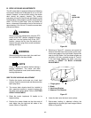
15. From the front of the tractor, push the PTO belt
through the front lift rod, then to the center of the
deck. Ensure that the forward end of the belt
remains positioned inside the front lower pulleys.
16. Install the rearward end of the PTO belt on the
upper pulley of the deck center double-pulley
(Refer to Figure 39). Ensure that the narrow side
of the belt engages the groove of the upper pulley,
and that there is no more than a 1/4 twist in the belt
between the front pulleys and the double pulley.
LIFT LINKS
(BOTH SIDES)
LIFT LINK HOLE
(BOTH SIDES)
DECK SUPPORT
PIN ENGAGED
SLOT IN REAR
DECK BRACKET
IDLER ARM
LEVER
STOP
BRACKET
PTO
CLUTCH
PULLEY
PTO
BELT
TRACTOR FRONT
LOWER PULLEYS
PTO BELT
FRONT LIFT
ROD/BRACKET
ASSEMBLY