


21
1
2
3
4
5
6
7
8
9
10
5
CONTROL
CAM
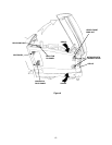
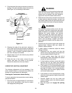
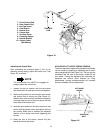
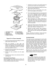
Adjusting the Control Rod
After completing the previous steps (1 thru 4) for
checking neutral setting, adjust the control rod ( See
Figure 15) as follows:
NOTE
The brake pedal lock MUST be engaged to
properly adjust the control rod.
1. Loosen, but do not remove, the hex tap screws
that fasten the front and rear control rods together.
2. While making certain to not move the front control
rod, control cam or control arm (See Figure 15),
slide the rear control rod in the direction necessary
to directly align the pin of the pivot sleeve with the
lower hole of the control arm.
3. Insert the pivot sleeve pin into the control arm and
secure with the hairpin cotter, then tighten the hex
tap screws. Make sure to maintain the adjusted
position of the control rods when tightening the
screws.
4. Raise the rear of the tractor, remove the jack
stands and lower the tractor.
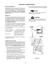
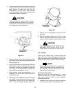
ADJUSTING LIFT ASSIST SPRING TENSION
The effort required to operate the implement lift handle
can be varied by loosening or tightening the lift assist
spring adjusting bolt (See Figure 16). The bolt can be
accessed from the rear of the tractor, inside the left
rear wheel. Turning the adjusting bolt clockwise will
decrease the manual effort required for lifting
attachments; turning counterclockwise will increase
the effort needed to lift the attachment.
Figure 16
LIFT ASSIST
SPRING
ADJUSTING
BOLT
1. Front Control Rod
2. Rear Control Rod
3. Hex Tap Screw
4. Pivot Sleeve
5. Neutral Arm
6. Control Arm
7. Hex Cap Screw
8. Centering Spacer
9. Neutral Bracket
10. Hairpin Cotter
(Not Shown)
Figure 15.