


12
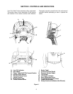
Q. SAFETY INTERLOCK SWITCHES
This tractor is equipped with a safety interlock system
for the protection of the operator. If the interlock sys-
tem should ever malfunction, do not operate the trac-
tor. Contact your authorized Cub Cadet Dealer. The
safety interlock system prevents the engine from
cranking or starting unless the brake pedal is fully de-
pressed, and the PTO switch is in the “OFF” position.
The safety interlock system will automatically shut off
the engine if the operator leaves the seat before en-
gaging the brake lock.
The safety interlock system will automatically shut off
the engine if the operator leaves the seat with the PTO
in the “RUN” position, regardless of whether the brake
lock is engaged. The PTO switch must be moved to the
“OFF” position to restart the engine.
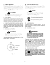
The safety interlock system will automatically shut off
the PTO if the reverse control pedal is depressed with
the PTO in the “RUN” position. To re-engage the PTO,
release the reverse control pedal, move the PTO
switch to the “OFF” position, then again pull the switch
to the “RUN” position.
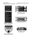
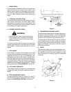
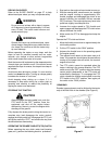
FUEL TANK
The fuel tank is located under the rear fender. The filler
cap is in the center/rear of the fender (see Figure 7).
Figure 7
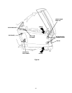
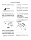
HOOD AND SIDE PANELS
The tractor hood is arranged to swing up and forward
for easy access to the engine compartment (see Fig-
ure 8). Whenever engine maintenance is required, the
side panels can be removed.
WARNING
If the engine has been recently run, the engine,
muffler and surrounding metal surfaces will be
hot and can cause burns to the skin. Allow the
tractor to cool and use caution when removing
the side panels.
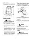
To remove either the right or left side panel, refer to
Figure 8 and proceed as follows:
1. Engage the brake lock and raise the hood.
2. Loosen, but do not remove, the rear wing nut and
upper front wing nut.
3. Grasp the side panel just behind the grille and pull
outward to release the side panel from the
tapered bushings on the grille.
4. Slide the side panel forward and out of the groove
in the dash panel.
To install either the right or left side panel, refer to Fig-
ure 8 and proceed as follows:
1. Slide the rear of panel into the groove in the dash
panel.
2. Position the notch of the rear side panel tab on
the threads of the bulkhead rod, between the
bulkhead and wing nut.
3. Press the slots of the front side panel flange onto
the tapered retainers, between the retainers and
the grille.
4. Tighten the rear and upper front wing nuts and
close the hood.