


Unpacking
1. Remove screws from the top sides and ends of the
shipping crate.
2. Set crate panels aside to avoid tire punctures or
personal injury.
3. Remove and discard plastic bag that covers unit.
4. Remove any loose parts included with unit (i.e.,
Operator's Manual, etc).
5. Roll unit out of crate.
Hardware Pack
Following items make up the hardware pack for your
snow thrower:
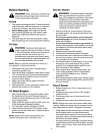
1. Shear bolts and lock nuts (2)
The augers are secured to the auger
shaft with two shear bolts and hex
lock nuts. Ifyou hit a foreign object
or icejam, these bolts may shear.
Two replacement shear boltsand
lock nuts are provided for your
convenience. Save these until
needed.
2. Z fittings and hex nuts (2)
These four hardware pieces will be
required inthe assembly ofthe snow
thrower. Identify the items and use
as instructed.
®
®
Hardware not drawn
to size here
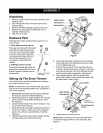
Setting Up The Snow Thrower
Your snow thrower was fully assembled at the factory
and needs minimum set-up.
NOTE: All references in this manual to left, right, top or
bottom is from the operating position only. Exceptions, if
any, will be specified.
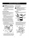
1. Disconnect spark plug wire and ground it against
the engine to prevent unintended starting.
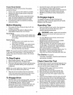
2. Remove hand knob A, cupped washer and carriage
screw from the lower handle. See Figure 1. Save
the hardware.
3. Loosen hand knobs B and C, shown in Figure 1, but
do not remove from the unit.
4. Raise the handle assembly up following direction of
the arrow in Figure 1. Make sure not to scrape the
paint on the unit by the eyebolt when you flip the
handle up.
5. Align the lower hole on each upper handle with the
corresponding hole on the lower handle.
Hand Knob B
Upper
Handle
Figure 1
6. Secure the right upper handle to the lower handle
with handle knob A and hardware removed in step
2. Do not tighten the knob.
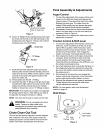
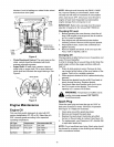
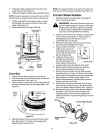
7. Remove the hand knob on the eye bolt and pivot
eye bolt in the direction shown in Figure 2. Insert the
eye bolt into the lower hole of the left upper handle
and the lower handle respectively. See Figure 2.
8. Place cupped washer, with the concave side
against the handle, on the eye bolt and secure with
the hand knob D. See Figure 2.
Lower Handle
Upper
Hand Knob
Handle
ye
bolt from here
Directional
Control
Figure 2
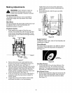
9. Tighten all four hand knobs now.
NOTE: Make sure that spiral on the chute directional
control fully engages teeth on chute assembly. See
Figure 3.