


Making Adjustments
_bb WARNING: Never attempt to make any
adjustments while the engine is running,
except where specified in operator's manual.
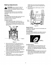
Chute Assembly
The distance snow is thrown can be controlled by
adjusting the angle of the top section of the chute
assembly.
Skid Shoe
The space between the shave plate and the ground can
be adjusted. Refer to the Final Assembly and
Adjustments section on page 6.
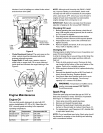
Traction Control
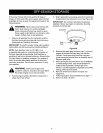
1. Drain gasoline and engine oil from the snow
thrower. Place plastic film under the gas cap if the
snow thrower has already been operated. Tip the
snow thrower so that it rests on the auger housing.
See Figure 17.
Fram_
.
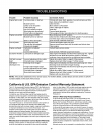
Tighten the lock nut to secure the cable when
correct adjustment is reached. Reassemble the
frame cover.
If you placed plastic under the gas cap earlier,
remove it now.
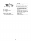
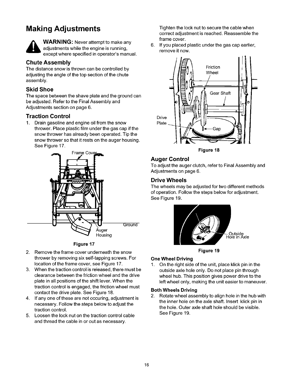
Figure 18
Auger Control
To adjustthe auger clutch, refer to Final Assembly and
Adjustments on page 6.
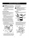
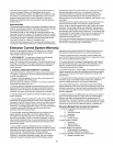
Drive Wheels
The wheels may be adjusted for two different methods
ofoperation. Follow the steps below for adjustment.
See Figure 19.
_round
Housing
Figure 17
2. Remove the frame cover underneath the snow
thrower byremoving six self-tapping screws. For
location of the frame cover, see Figure 17.
3. When thetraction control isreleased, there must be
clearance between the friction wheel and the ddve
plate in all positions of the shift lever. When the
traction controlis engaged, the friction wheel must
contact the drive plate. See Figure 18.
4. Ifany one of these are not occuring, adjustment is
necessary. Followthe steps below to adjust the
traction control.
5. Loosen the lock nuton the traction controlcable
and thread the cable in or out as necessary.
Figure 19
One Wheel Driving
1. On the right side of the unit, place ktick pin in the
outside axle hole only. Do not place pin through
wheel hub. This position gives power drive to the
left wheel only, making the unit easier to maneuver.
Both Wheels Driving
2. Rotate wheel assembly to align hole in the hub with
the inner hole on the axle shaft. Insert klick pin in
the hole. Outer axle shaft hole should be visible.
See Figure 19.
16