


FdcUon
Bearing
Bolts
Fasteners
i
i
i--
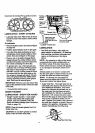
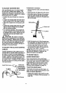
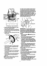
Unit Standingon Auger HousingEnd
• Remove right side bearing plate. Leave
hex shaft in original position.
• Remove friction wheel from hub. Slip fric-
tion wheel oft hex shaft towards right side.
See figure below.
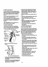
• Position new friction wheel onto hub. See
Figure below.
Friction Wheel
Shaft
Bolt
Nut
• install bearing plates to original position.
Ensure hex shaft is engaged with both
bearing plates.
• Secure bearing plates, using bolts re-
moved earlier.
• Secure friction.wheel to hub using fasten-
ers removed earlier. Ensure hex shaft
tums freely.
• Should friction wheel require adjustment
(see To Adjust the Friction Wheel on
page 20).
NOTE: Ensure friction wheel and friction
disc are free from grease or oil."
• Replace bottom panel•
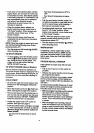
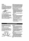
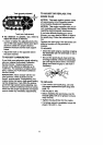
TO REPLACE AUGER SHEAR BOLT
The augers are secured to the auger shaft
with special bolts (see figure below) that are
designed to break (to protect the machine) if
an object becomes lodged in the auger
housing. Use of a harder bolt will destroy the
protection provided by the shear bolt. Your
replacement shear bolts are found in your
tool box located on belt cover.
IMPORTANT: To ensure safety and perfor-
mance levels, only originalequipment shear
boltsshouldbe used. When replacingshear
bolts, be sure to replace shear bolt spacers.
To replace a broken shear bolt, proceed as
follows:
• Move the throttle to O (STOP) and turn
off all controls.
Disconnect the spark plug wire. Be sure
all moving parts have stopped.
Lubricate the auger shaft by squirting
Lubriplate or a fiber impregnated grease
into the shear bolt hole in the auger shaft.
Then rotate the auger to distribute the oil
in the shaft.
• Align the hole in the auger tube with the
hole in the auger shaft, install the new
shear pin and spacer found in toolbox lo-
cated on top of belt cover.
NOTE: Spacer fits inside the larger hole in
the auger tube.
• Reconnect the spark plug wire.
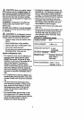
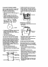
TO ADJUST TRACK
it the snow thrower does not move forward
evenly and the track slips slightly, you need to
check the track as follows:
• Pull up gently on the center of the track
near the center.
• Measure the distance between the track
and the top of the track support frame
(see first figure on page 22). The
distance should not be more than one and
one-quarter (1-1/4) inches.
21