


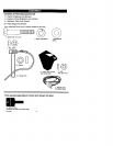

TO ASSEMBLE THE HANDLEAND
CRANK ASSEMBLY
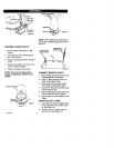
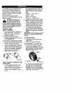
t. Loosen, but do not remove, the
screws, flatwashers, Iockwashers,
and hex nuts in the upper holes of
the lower handle. See Figure 3.
Right Hand Side
Of L
3/8" Hex
Loosen, Nut
but do not*,,
remove
3/8" Flat-
Hex Nut,
3/8 x 2"
Screw
3/8"
Figure 3
NOTE: Make sure the cables are not
caught between the upper and lower
handle.
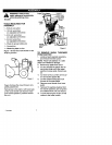
2. Raise the upper handle into operat-
ing position. Upper handle should
be to the outside of the lower han-
die.
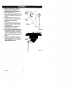
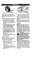
NOTE: Ifthe cables have become dis-
connected form the clutch levers, rein-
stall the cables as shown in Figure 4.
Clutch L_
Cont;cZ"IFitly, J
Cable _(_/
Figure 4
3. Install hardware supplied in the
parts bag (screw, flatwasher, Iock-
F-O01060J
washer, and hex nut) into bottom
hole on right hand side of handles.
DO NOT tighten until all bolts are in
place.
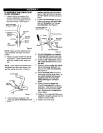
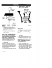
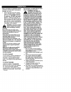
4. Locate crank assembly removed
earlier and remove the nylon lock-
nut and flatwasher from the eye
bolt assembly. See Figure 5.
Left Hand Side Of
Upper Handle
3/8" Nylon
, Locknut
8
3/8"
3/8" Flatwasher
Figure 5
5. Reinstall flatwasher and adaptor.
Install eye bolt through lower hole
on the left hand side of the handle.
6. Install the 3/8" flatwasher and the
3/8" nylon Iocknut loosely on the
eye bolt.
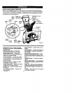
7. Carefully remove cotter pin, clevis
pin and universal joint pin from
yoke end of crank rod assembly.
See Figure 6.
8. Place universal joint into end of
worm gear lining up Large holes. In-
sert universal joint pin (ensure
opening in pin Is In line with
small openings In universal
joint).
9. Place yoke end of crank rod
around universal Joint, lining up
openings. Insert clevis pin through
assembly and secure with cotter
pin. Spread ends of cotter pin to
lock in place.
10. Tighten nut on eye bolt. Make sure
eye bolt is properly aligned and the
crank can freely rotate.
11. Tighten all handle bolts.