


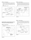

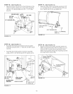
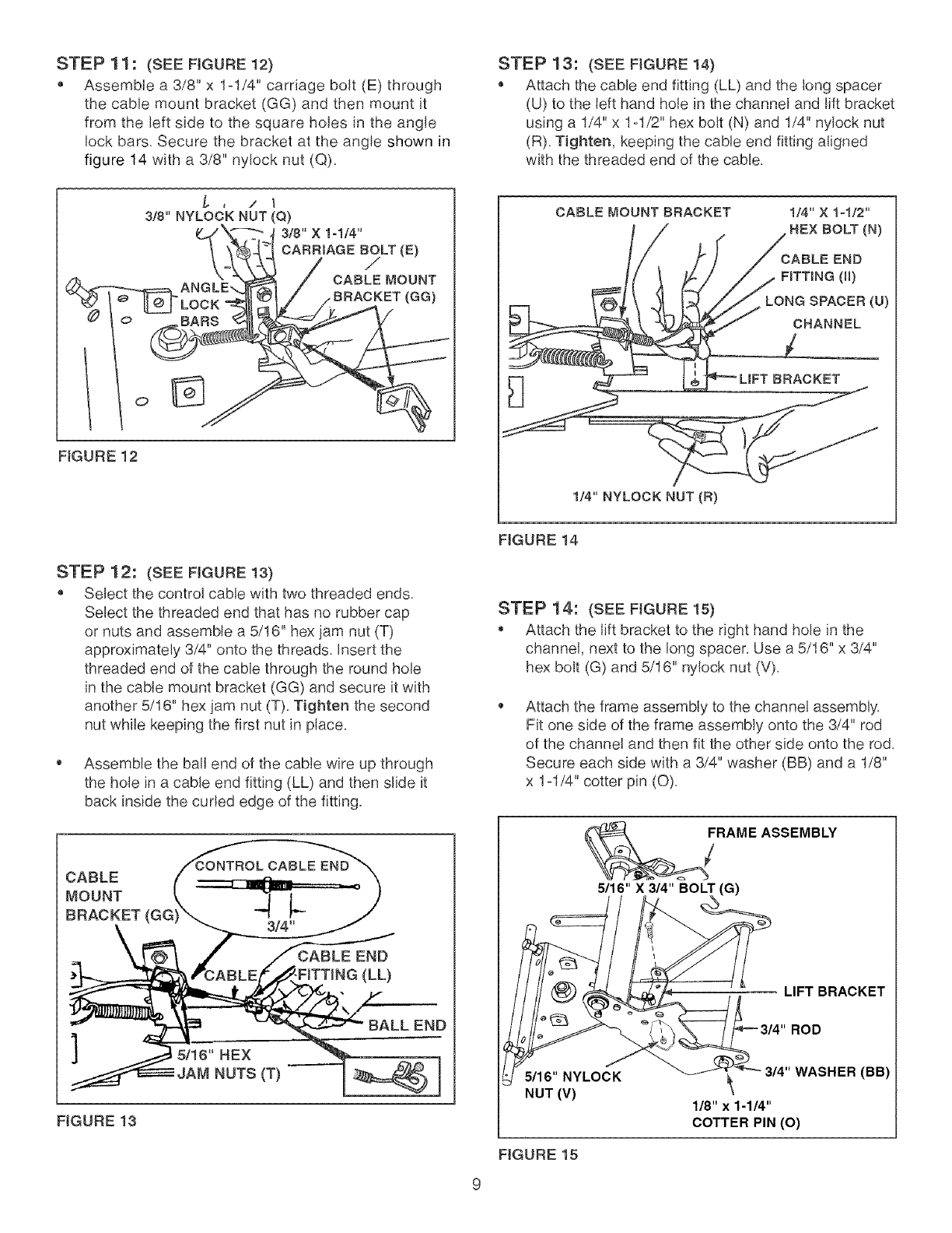
STEP 11: (SEE FIGURE 12)
o Assemble a 3/8" x 1ol/4" carriage bolt (E) through
the cable mount bracket (GG) and then mount it
from the left side to the square holes in the angle
lock bars, Secure the bracket at the angle shown in
figure 14 with a 3/8" nylock nut (Q).
3/8" NYLOCK NUT (Q)
_ LOCK-_._I _ I / BRACKET (GG)/,
O
FIGURE 12
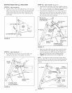
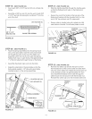
STEP 13: (SEE FIGURE 14)
Attach the cable end fitting (LL) and the long spacer
(U) to the left hand hole in the channel and lift bracket
using a 1/4" x 1ol/2" hex bolt (N) and 1/4" nylock nut
(R)=Tighten, keeping the cable end fitting aligned
with the threaded end of the cable.
CABLE MOUNT BRACKET 1/4" X 1-1/2"
HEX BOLT (N)
CABLE END
FiTTiNG (ll)
LONG SPACER(U)
CHANNEL
cKET
1/4" NYLOCK NUT (R)
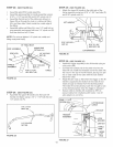
STEP 12: (SEE FIGURE 13)
Select the control cable with two threaded ends,
Select the threaded end that has no rubber cap
or nuts and assemble a 5/16" hex jam nut (T)
approximately 3/4" onto the threads, Insert the
threaded end of the cable through the round hole
in the cable mount bracket (GG) and secure it with
another 5/16" hex jam nut (T). Tighten the second
nut while keeping the first nut in place.
Assemble the ball end of the cable wire up through
the hole in a cable end fitting (LL) and then slide it
back inside the curled edge of the fitting.
]
5/16" BEX
(T)
BALL END
FIGURE 13
FIGURE 14
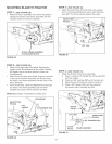
STEP 14: (SEE FIGURE 15)
Attach the lift bracket to the right hand hole in the
channel, next to the long spacer, Use a 5/16" x 3/4"
hex bolt (G) and 5/16" nylock nut (V).
Attach the frame assembly to the channel assembly.
Fit one side of the frame assembly onto the 3/4" rod
of the channel and then fit the other side onto the rod.
Secure each side with a 3/4" washer (BB) and a 1/8"
x 1ol/4" cotter pin (O).
FRAME
5/16" X 3/4" BOLT (G)
ASSEMBLY
LIFT BRACKET
ROD
5116" NYLOCK
NUT (V)
314"WASHER (BB)
118" x 1-114"
COTTER PIN (O)
FIGURE 15