


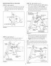
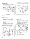
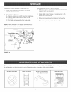


MOUNTING BLADE TO TRACTOR
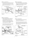
STEP 1: (SEE FIGURE 28}
, Attach the frame assembly to the frame brackets by
sliding the notches in the frame assembly onto the
shouJder boJts on the frame brackets.
L9
ATTACH FRA[tvIE ASSEMBLY
TO SHOULDER BOLTS
FIGURE 28
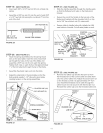
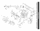
STEP 3: (SEE FIGURE 30)
, Attach the small holes of the Jift Jinks to the weJded
pins on the frame bracket and secure with haircotter
pins (KK), The lift link should angle to the inside,
HA{RCOTTER
PmN(KK)
LUFTLiNK
FIGURE 30
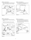
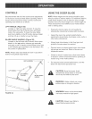
STEP 2: (SEE FIGURE 29)
, Stand on the right side of the blade. Squeeze the
trigger on the lift handle and Jiftthe handle. Release
the trigger, but do not al!ow handle to lower into
locked position.
, Stand on the left side of the blade. Grip the round bar
at the top of the frame assembly and lift up to align
the hoJes in the frame assembly with the holes in the
frame brackets.
, From the left side, insert the attachment rod through
the holes in the frame assembly and the frame
brackets and secure with a haircotter pin (KK).
NOTE: Blade hidden in illustration for better view.
HAIROOTTER
PIN (KK)
LiFT
ROUND BAR
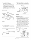
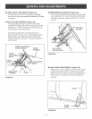
STEP 4: (SEE FIGURE 31)
, Attach the lift Jinks to the frame assembly:
A. Insert a clevis pin (ll) through the frame assembly
from the outside.
B. Place two 5/8" washers (DD) onto the clevis pin.
C. PJace the end of the lift tink onto the cJevis pin.
D. Place a 5/8" washer (DD) onto the clevis pin
and secure with a haircotter pin (KK).
LiFT LmNK
HAIRCOTTER
CLEVUS
PiN (m0 FRAME ASSEMBLY
FIGURE 31
FIGURE 29
13