


iNSTRUCTiONS FOR ALL TRACTORS
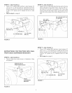
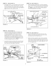
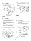
STEP 8: (SEE FIGURE 8)
', Install a 1/2" x 2" hex bolt (B) and two 1/2" hex nuts
(W) in the outer hole in each side of the pivot plate.
Temporarily adjust the hex nuts so that both bolt
heads extend about an inch and a half above the
pivot plate.
1/2" X 2" BOLT (B)
)
112" HE× NUTS (W)' _
io
c
,©
"o
FIGURE 8
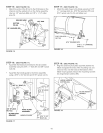
STEP 9: (SEE FIGURE 9)
,, Assemble the round hook end of the angle lock
spring into the hole in the washer as shown,
Q
WASHER
ANGLELOCK
SPRmNG
CHANNEUPIVOT
PLATE ASSEMBLY
FIGURE 9
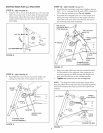
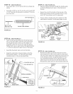
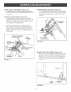
STEP 10: (SEE FIGURE 10 and 11)
', Assemble the two angle lock bars together using a
3/8" x 1ol/4" carriage bolt (E) and a 3/8" nylock nut
(Q) in the top square hole& Do not tighten.
', Assemble the straight hook end of the angle lock
spring into the small holes in the angle lock bars.
Insert the lock bars down into the lock bar slot in
the channel pivot plate assembly.
3/8" X 1ol/4"
CARRIAGE BOLT
(TOP HOLE) (E)
\
3/8" NYLOCK
ANGLELOCK
FRONT
LOCKBAR
SLOT
SPRRNG P_N
ANGLE LOCK
SPR_NG HOLE
CHANNEL/PIVOT
PLATE ASSEMBLY
FIGURE 10
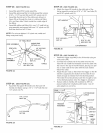
Align the angle lock bars with the welded bracket
on the bottom of the channel, Use a hammer to
drive the spring pin (NN) through the angle lock
bars and into the slot in the welded bracket.
Tighten the nylock nut on the carriage bolt.
NOTE: The angle lock bars should pivot freely, When
they are pulled all the way back the pivot plate assembly
should be unlocked and free to pivot to the right or left
notches.
-_,_FRONT ANGLE
LOCK BARS
G
@
LOCK
BARS
1/4"' X l"'
SPRING PIN (NN}
FIGURE 11
8