


2.
With your multimeter set to DC Volts, verify tha
VDC at TP6 (Positive lead) and TP3 (Negative Lead) as indicated in Figure 22. If the Power Supply
Output Voltage is greater than 30
drops below 30-
VDC before you proceed with the next step.
3.
Carefully remove the input and output cables from the failed
connected to the
LED MODULE
MODULE
is denoted by a black arr
4.
Loosen and remove the nuts on the
MODULE
bracket bolts with one hand while support the
5. Carefully remove the failed
LED MODULE
6. Mount the replacement
LED MODULE
MODULE
heat sink are aligned with the mounting bracket holes. (Note: The replacement
MODULE input connecto
r should be closest to the marked input cable connector.)
7.
Push the mounting bracket bolts through the mounting bracket and the
holes.
8.
Attach nuts to the mounting bracket bolts and tighten.
9.
Gently slide the input cable connecto
10.
Likewise, slide the output cable connector into the replacement
housing.
11. The LED MODULE
replacement is complete
12.
Power Supply Board must be re
IMPORTANT
Power Supply Board must be re
Instruction Manual
AGS-LED
858 LED Series
Sizes 1, 2, 3, 4 and 5
16
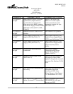
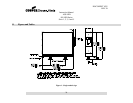
With your multimeter set to DC Volts, verify tha
t the Power Supply Output Voltage is less than 30
VDC at TP6 (Positive lead) and TP3 (Negative Lead) as indicated in Figure 22. If the Power Supply
Output Voltage is greater than 30
-
VDC, then you must wait until the Power Supply Output Voltage
VDC before you proceed with the next step.
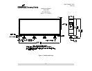
Carefully remove the input and output cables from the failed
LED MODULE
. (Mark the cable
LED MODULE
input connector. Note:
The input connector on the
is denoted by a black arr
ow pointing toward the input connector
(see Figure 7).
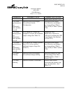
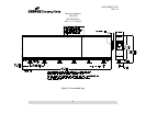
Loosen and remove the nuts on the
LED MODULE
mounting bracket bolts. Remove the
bracket bolts with one hand while support the
LED MODULE
with your other hand.
LED MODULE
from the LED MODULE
mounting bracket.
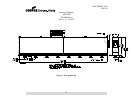
LED MODULE
into the mounting bracket such that the holes in the
heat sink are aligned with the mounting bracket holes. (Note: The replacement
r should be closest to the marked input cable connector.)
Push the mounting bracket bolts through the mounting bracket and the
LED MODULE
Attach nuts to the mounting bracket bolts and tighten.
Gently slide the input cable connecto
r into the replacement LED MODULE
connector input housing.
Likewise, slide the output cable connector into the replacement
LED MODULE
output connector
replacement is complete
.
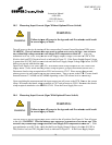
Power Supply Board must be re
-calibrated aft
er replacing an LED MODULE (see Section 10.
WARNING:
Power Supply Board must be re
-
calibrated after replacing an
LED MODULE (see Section 10.11).
DOCUMENT 1025
REV. B
t the Power Supply Output Voltage is less than 30
-
VDC at TP6 (Positive lead) and TP3 (Negative Lead) as indicated in Figure 22. If the Power Supply
VDC, then you must wait until the Power Supply Output Voltage
. (Mark the cable
The input connector on the
LED
(see Figure 7).
mounting bracket bolts. Remove the
LED
with your other hand.
mounting bracket.
into the mounting bracket such that the holes in the
LED
heat sink are aligned with the mounting bracket holes. (Note: The replacement
LED
LED MODULE
heat sink
connector input housing.
output connector
er replacing an LED MODULE (see Section 10.
11).
calibrated after replacing an