


Turn off power to the sign by turning off the corresponding Constant Current Regulator (CCR) power.
(WARNING: W
ait five minutes after sign power is turned off
any residual high voltage
stored in Power Supply
multimeter set to DC Volts, verify that the Power Supply Output Voltage is
(Positive lead) and TP3 (Negative Lead) as indicated in Figure 22. If the Power Supply Output Voltage
is greater than 30-
VDC, then you must wait until the Power Supply Output Voltage drops below 30
before you proceed with the
next step.
Remove the
black return cable connector
Figures 7-11 & 20). Replace
the output cable connector in the first
cable connector.
Turn on main power. If the firs
then the first LED MODULE
and the Power Supply LED cable and Power Supply board are operating
normally.
Turn off main power to the sign. Wait five minutes for the power supply voltages to dissipate.
the output voltage is less than 30-
VDC with a multimeter as described in the opening paragraph of this
section. Replace the
black return cable connector
If the sign does not light at all, then re
output of the Power Supply
to the input of LED MODULE #
described above in this section.
10.8 Checking the Second
LED MODULE
WARNING
Failure
to turn off power to the sign and wait five minutes could result
in severe injury or death.
Turn off power to the sign by turning off the corresponding Constant Current Regulator (CCR) power.
(WARNING: W
ait five minutes after sign power is turned off
any residual high voltage
stored in Power Supply
multimeter set to DC Volts, verify that the Power Supply Output Voltage is less than 30
(Positive lead) and TP3 (Negati
ve Lead) as indicated in Figure 22. If the Power Supply Output Voltage
is greater than 30-
VDC, then you must wait until the Power Supply Output Voltage drops below 30
before you proceed with the next step.
Remove the
black return cable connector
20). R
eplace the output cable connector in the second
connector
. Turn on main power to the sign.
Instruction Manual
AGS-LED
858 LED Series
Sizes 1, 2, 3, 4 and 5
13
Turn off power to the sign by turning off the corresponding Constant Current Regulator (CCR) power.
ait five minutes after sign power is turned off
to service the sign
. This will allow
stored in Power Supply
PCB components to bleed off
.) With your
multimeter set to DC Volts, verify that the Power Supply Output Voltage is
less than 30
(Positive lead) and TP3 (Negative Lead) as indicated in Figure 22. If the Power Supply Output Voltage
VDC, then you must wait until the Power Supply Output Voltage drops below 30
next step.
black return cable connector
from the last LED MODULE
output cable connector
the output cable connector in the first
LED MODULE
with the
Turn on main power. If the firs
t LED MODULE
momentarily lights and then turns off,
and the Power Supply LED cable and Power Supply board are operating
Turn off main power to the sign. Wait five minutes for the power supply voltages to dissipate.
VDC with a multimeter as described in the opening paragraph of this
black return cable connector
with the first LED MODULE
output cable connector.
If the sign does not light at all, then re
place the LED MODULE #1 and/or the cable connecting from the
to the input of LED MODULE #
1(see Section 10.10)
. Then
LED MODULE
WARNING:
to turn off power to the sign and wait five minutes could result
in severe injury or death.
Turn off power to the sign by turning off the corresponding Constant Current Regulator (CCR) power.
ait five minutes after sign power is turned off
to service the sign
. This will allow
stored in Power Supply
PCB components to bleed off.
) With your
multimeter set to DC Volts, verify that the Power Supply Output Voltage is less than 30
ve Lead) as indicated in Figure 22. If the Power Supply Output Voltage
VDC, then you must wait until the Power Supply Output Voltage drops below 30
before you proceed with the next step.
black return cable connector
from the last LED MODULE
output cable connector (see Figure
eplace the output cable connector in the second
LED MODULE with the
black return cable
. Turn on main power to the sign.
If both LED MODULES
momentarily light and then turn off
DOCUMENT 1025
REV. B
Turn off power to the sign by turning off the corresponding Constant Current Regulator (CCR) power.
. This will allow
.) With your
less than 30
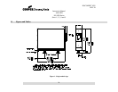
-VDC at TP6
(Positive lead) and TP3 (Negative Lead) as indicated in Figure 22. If the Power Supply Output Voltage
VDC, then you must wait until the Power Supply Output Voltage drops below 30
-VDC
output cable connector
(see
with the
black return
momentarily lights and then turns off,
and the Power Supply LED cable and Power Supply board are operating
Turn off main power to the sign. Wait five minutes for the power supply voltages to dissipate.
Verify that
VDC with a multimeter as described in the opening paragraph of this
output cable connector.
place the LED MODULE #1 and/or the cable connecting from the
. Then
repeat the test
to turn off power to the sign and wait five minutes could result
Turn off power to the sign by turning off the corresponding Constant Current Regulator (CCR) power.
. This will allow
) With your
multimeter set to DC Volts, verify that the Power Supply Output Voltage is less than 30
-VDC at TP6
ve Lead) as indicated in Figure 22. If the Power Supply Output Voltage
VDC, then you must wait until the Power Supply Output Voltage drops below 30
-VDC
output cable connector (see Figure
black return cable
momentarily light and then turn off