


d.
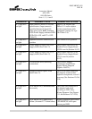
The concrete foundation/pad should be not more than 1 inch above grade in or
inch maximum overall height above grade to the point of frangibility per FAA Engineering
79. See the Engineering Brief for acceptable grading around the foundation/pad. The foundation/pad
pad must be level.
e. It is re
commended that the contractor who is to install the concrete foundation/pad use cast in place
anchor bolts. The threaded portion of the anchor bolts should be 1
maximum above the top of the concrete foundation/pad
the anchor bolts be installed accurately as shown in the concrete foundation/pad dimensions
13.
The clearance holes on the floor flange are 5/8 inch diameter on a 4.75 inch diameter bolt circle
for use with ½ inch anc
hor bolts.
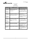
f.
The concrete foundation/pad should include the series isolation transformer housing. It is
recommended that this housing
isolation transformer and connections for ease of
12c).
This housing would be on the side closest to the Taxiway or Runway. A 2 inch conduit elbow
with threaded coupling attached at sign end would exit from the transformer housing side to the
foundation/pad
and be flush with the with the top of the concrete foundation/pad
between the floor flange bolts nearest the Taxiway or Runway side of the sign. The sign as viewed
will have the circuit card box to the right on the “
or Runway side of the sign. If the location requires an add
messages, then the separation distance between these signs housings can be 3 inches minimum to 12
inches maximum (FA
A AC 150
adjacent Taxiway) will have the circuit card box to the left on the “A” side of the sign. The sign side
identification is important with regards to its sign panel legend. A g
be installed at the end opposite the circuit card box in order to ground the sign housing. This
grounding rod must not be connected to the field counterpoise.
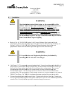
DANGER
Lock out electrical power to the series loop
its source before attempting any electrical connections/splices.
g.
Make electrical connections to the series loop power using L
the primary connectors to the appropriate size L
These primary connections (single pin plug or receptacle) should have Heat Shrink Kits applied over
their connections to prevent disconnection and water from entering the cables. If two Series Isolation
Transforme
rs are required to be attached in series to obtain the correct wattage required for the sign,
all primary lead connections should have Heat Shrink Kits applied. Two Series Isolation
Transformers connected in series together will require a Consolidating Ha
Number 26811-27)
at the transformer secondary connectors (two pin receptacle) to series them
together.
Use electrical tape around the connections to prevent accidental disconnection. The Series
Instruction Manual
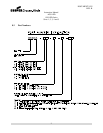
AGS-LED
858 LED Series
Sizes 1, 2, 3, 4 and 5
4
The concrete foundation/pad should be not more than 1 inch above grade in or
der to maintain the 3
inch maximum overall height above grade to the point of frangibility per FAA Engineering
79. See the Engineering Brief for acceptable grading around the foundation/pad. The foundation/pad
commended that the contractor who is to install the concrete foundation/pad use cast in place
anchor bolts. The threaded portion of the anchor bolts should be 1
-
5/8 inches minimum to 1
maximum above the top of the concrete foundation/pad
(See Figures 12, 12a-12c).
This requires that
the anchor bolts be installed accurately as shown in the concrete foundation/pad dimensions
The clearance holes on the floor flange are 5/8 inch diameter on a 4.75 inch diameter bolt circle
hor bolts.
The concrete foundation/pad should include the series isolation transformer housing. It is
recommended that this housing
not be
placed under the sign power leg to allow access to the series
isolation transformer and connections for ease of
troubleshooting and servicing (
See Figure
This housing would be on the side closest to the Taxiway or Runway. A 2 inch conduit elbow
with threaded coupling attached at sign end would exit from the transformer housing side to the
and be flush with the with the top of the concrete foundation/pad
grade level centered
between the floor flange bolts nearest the Taxiway or Runway side of the sign. The sign as viewed
will have the circuit card box to the right on the “
A” side of th
e sign, which is closest to the Taxiway
or Runway side of the sign. If the location requires an add
itional housing to accommodate
messages, then the separation distance between these signs housings can be 3 inches minimum to 12
A AC 150
-5345-
44J 3.2.5.2 a.). This first sign body housing (farthest from the
adjacent Taxiway) will have the circuit card box to the left on the “A” side of the sign. The sign side
identification is important with regards to its sign panel legend. A g
rounding rod and clamp should
be installed at the end opposite the circuit card box in order to ground the sign housing. This
grounding rod must not be connected to the field counterpoise.
DANGER:
Lock out electrical power to the series loop
that will power the sign at
its source before attempting any electrical connections/splices.
Make electrical connections to the series loop power using L
-
823 Primary Connector Kits. Attach
the primary connectors to the appropriate size L
-830 Series Isolation Transformer
(See Tables 3
These primary connections (single pin plug or receptacle) should have Heat Shrink Kits applied over
their connections to prevent disconnection and water from entering the cables. If two Series Isolation
rs are required to be attached in series to obtain the correct wattage required for the sign,
all primary lead connections should have Heat Shrink Kits applied. Two Series Isolation
Transformers connected in series together will require a Consolidating Ha
rness
(Crouse
at the transformer secondary connectors (two pin receptacle) to series them
Use electrical tape around the connections to prevent accidental disconnection. The Series
DOCUMENT 1025
REV. B
der to maintain the 3
inch maximum overall height above grade to the point of frangibility per FAA Engineering
Brief no.
79. See the Engineering Brief for acceptable grading around the foundation/pad. The foundation/pad
commended that the contractor who is to install the concrete foundation/pad use cast in place
5/8 inches minimum to 1
-7/8
This requires that
the anchor bolts be installed accurately as shown in the concrete foundation/pad dimensions
Figure
The clearance holes on the floor flange are 5/8 inch diameter on a 4.75 inch diameter bolt circle
The concrete foundation/pad should include the series isolation transformer housing. It is
placed under the sign power leg to allow access to the series
See Figure
s 12, 12a-
This housing would be on the side closest to the Taxiway or Runway. A 2 inch conduit elbow
with threaded coupling attached at sign end would exit from the transformer housing side to the
grade level centered
between the floor flange bolts nearest the Taxiway or Runway side of the sign. The sign as viewed
e sign, which is closest to the Taxiway
itional housing to accommodate
multiple
messages, then the separation distance between these signs housings can be 3 inches minimum to 12
44J 3.2.5.2 a.). This first sign body housing (farthest from the
adjacent Taxiway) will have the circuit card box to the left on the “A” side of the sign. The sign side
rounding rod and clamp should
be installed at the end opposite the circuit card box in order to ground the sign housing. This
that will power the sign at
its source before attempting any electrical connections/splices.
823 Primary Connector Kits. Attach
(See Tables 3
-8).
These primary connections (single pin plug or receptacle) should have Heat Shrink Kits applied over
their connections to prevent disconnection and water from entering the cables. If two Series Isolation
rs are required to be attached in series to obtain the correct wattage required for the sign,
all primary lead connections should have Heat Shrink Kits applied. Two Series Isolation
(Crouse
-Hinds Part
at the transformer secondary connectors (two pin receptacle) to series them
Use electrical tape around the connections to prevent accidental disconnection. The Series